STANDARDS OF PRACTICE
The International Standards of Practice for inspecting the HVAC systems is located at www.nachi.org/sop.
SIZE AND CATEGORY
Gas appliances are categorized so that the proper venting system can be selected. There are four categories based upon the pressure produced in the vent and whether or not the flue gas temperatures create condensation.
You'll commonly find Category I and Category IV furnaces and boilers in U.S. houses. Category I does not produce condensate. Category IV operates with a positive vent pressure and condenses flue gases, and their flue vent pipes are made of PVC plastic.
Type B vents are designed for venting non-condensing gas appliances equipped with a draft hood or fan-assisted appliances with a non-positive vent pressure.
Heating and cooling equipment and appliances must be sized in accordance with the Manual S and Manual J of the Air Conditioning Contractors of America.
Observation
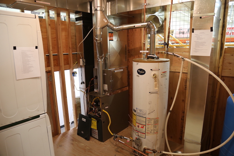
The furnace in the furnace room is a Category I appliance that operates under a negative or neutral vent pressure. It's not a condensing appliance. It uses a draft inducer fan.
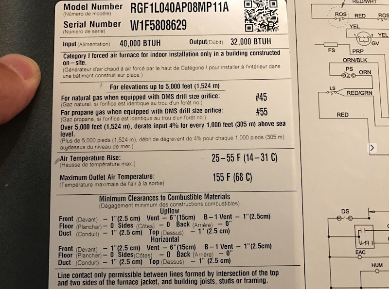
You may want to confirm this observation by checking the manufacturer's information sticker for the appliance. On this appliance, it's located at the front cover at the blower fan location.
Observation
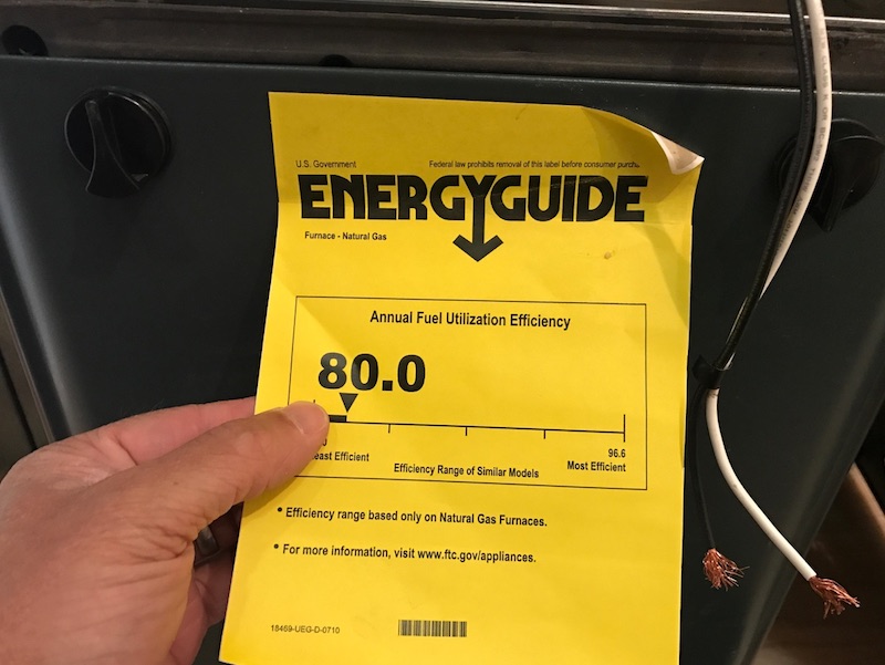
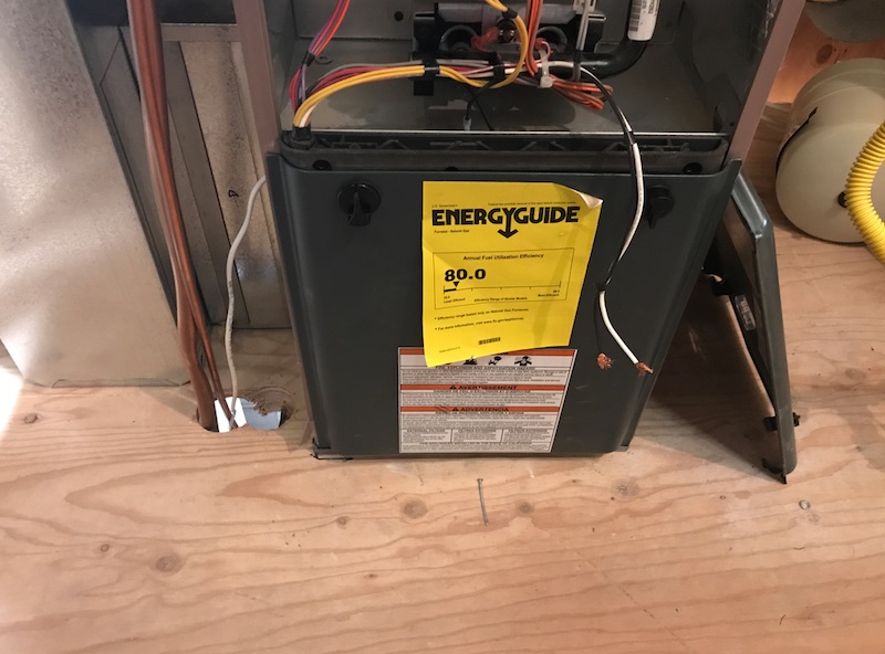
The furnace is 80% efficient. You may calculate the efficiency by dividing output BTU by input BTU on the manufacturer's data sticker. Or, there may be an efficiency sticker attached, such as the yellow sticker.
ACCESS
Heating and cooling equipment and appliances must be accessible for inspection, routine maintenance, repairs and replacements.
Observation
The manufacturer requires 24 inches in front of the appliance for access.
2015 IRC M1305 recommends that the furnace have a level working space of at least 30 inches by 30 inches in the front of the appliance. Municipalities may require a minimum of 30 clear inches in front of the furnace, which can be accomplished in a small room if the door to the room opens in front of the furnace.
The furnace in the furnace room is accessible for service.
Observation
There are combustible wall materials in close proximity to the gas-fired furnace appliance. According to the manufacturer, the minimum clearance from the back-side of the appliance is 0 inches.

AUXILIARY DRAIN PAN
Category IV appliances produce condensate. A condensing appliance must be provided with an auxiliary drain pan where structural damage to a home's building components may occur, if the condensate drainage leaks. A pan is not necessary if the appliance has an automatic shut-down device installed.
Observation
A pan is not needed at this installation.
CONDENSATE PUMP
Condensate pumps should be connected to the appliance such that when the pump fails, the appliance shuts off. The condensate pump should have an overflow shutoff capability.
Observation
There's no condensate drainage or pump installed for the central air conditioner's evaporator.
COMBUSTION AIR
Combustion air is necessary for the complete combustion of fuel gas, dilution of flue gases, and ventilation of gas-fired appliances and the space in which they are installed. A lack of combustion air can cause the incomplete combustion of fuel, malfunction of an appliance, and spillage of flue gases. Gas-fired appliances often compete with other equipment and systems for available combustion air and makeup air through a house. Supplying makeup air can help natural-draft appliances by compensating the effect of the powered exhaust appliances and equipment in the house, including fireplaces, exhaust fans, ventilation systems, clothes dryers and similar appliances and equipment.
There are five methods of supplying combustion air listed in the 2015 IRC G2407, ranging from simple to complex:
- all indoor air,
- all outdoor air,
- combination indoor and outdoor air,
- mechanical combustion air supply, and
- engineered design.
These methods of supplying combustion air applies mostly to natural-draft atmospheric-burner-design appliances and Category 1 fan-assisted appliances. Category 2, 3, and 4 appliances must be provided with combustion air as required by the manufacturer's instructions.
METHODS OF COMBUSTION AIR
Indoor Combustion Air
The required volume of indoor air to be used as combustion air is determined in five different ways according to 2017 IRC G2407.5, except when the infiltration rate is known to be less than 0.40 air exchanges per hour (ACH). The terms "confined space", "unconfined space", and "unusually tight construction" are no longer used.
Require volume of indoor air is determined by two methods, unless the known infiltration rate is less than 0.40 ACH:
- one is based upon the actual air infiltration rate measured in the house, and
- the other is based on the familiar 50 cubic feet per 1,000 Btu/h.
Openings to Connect Indoor Spaces
Where openings are used to connect adjacent indoor spaces on the same floor for the purpose of increasing the available volume of air, the familiar high and low openings may be provided. The openings must be permanently open, and each opening must be at least 100 square inches in size. One opening must be within 12 inches of the top and one opening 12 inches of the bottom of the enclosure.
Outdoor Combustion Air Opening
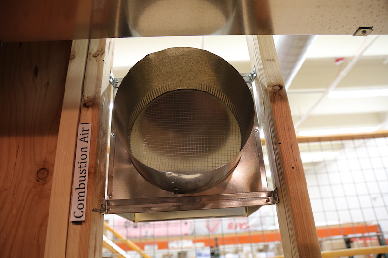
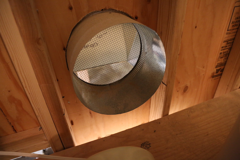
Openings directly connected to the outdoor air or to spaces that are naturally ventilated with outdoor air, such as crawlspaces or attics, are acceptable. The combustion air openings should be located to prevent blockage. The opening could be one-permanent opening or two-permanent high-low openings. There are various types of opening combinations that may include indoor and outdoor spaces to supply combustion air.
Not Required
Home inspectors are not required to calculate the air for combustion, ventilation, and dilution of flue gases for appliances.
Observation
The combustion air opening at the exterior wall of the furnace room may cause pipe freezing problems for cold climates.
Observation
There are 2 air registers on the exterior of the house, on the wall opposite the furnace room. One is blocked with debris.
MAKEUP AIR
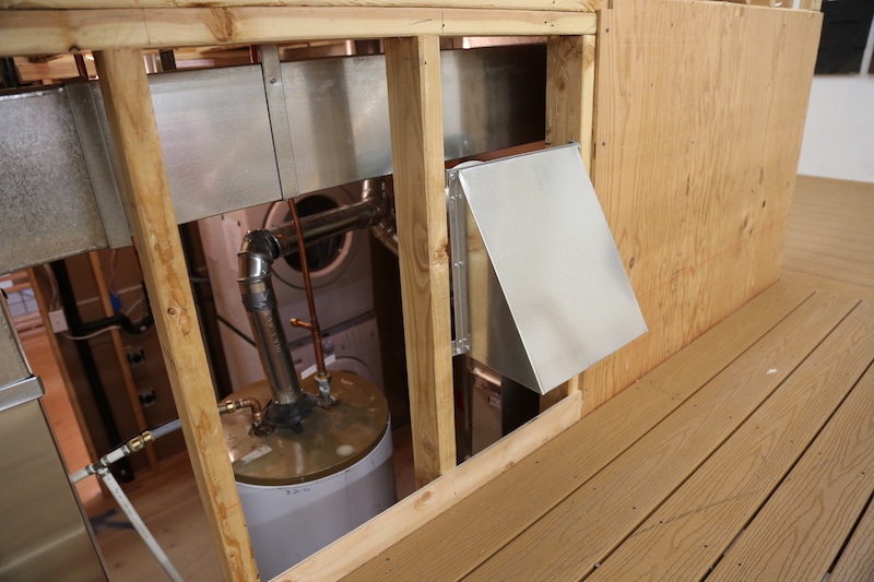
Makeup air is needed where clothes dryers, kitchen exhaust fans, chimneys, and other exhaust and ventilation systems may interfere with the appliance operation. Not enough makeup air may cause negative pressures to develop and may interfere with appliance venting, creating a loss of draft at appliance vents and chimneys or causing combustion byproducts to backdraft into the house. Gas-fired appliances are often in competition with other systems for the available combustion air and makeup air that flows through the house building envelope. And natural draft appliances could starve for air. Supplying makeup air will help prevent negative pressures with a space from developing.
Note the following systems that may deplete combustion air: bathroom exhaust fan at 80 CFM, range hood at 100 CFM, clothes dryer at 200 CFM, and a fireplace chimney at 600 CFM.
Observation
The combustion air opening at the exterior wall of the furnace room may cause pipe freezing problems for cold climates.
PROTECTION FROM FUMES
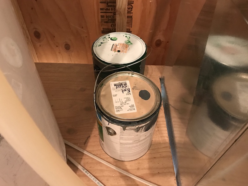
Chemicals that generate corrosive or flammable products should be removed from rooms providing combustion air and dilution air, particularly for natural draft appliances. Chemicals could contaminate the indoor combustion air by combining with water vapor in the combustion gases to produce acids that can damage appliance components, vents, chimneys and connectors.
Observation
There are cans of chemicals in the utility room. They should be removed to help prevent corrosion of the HVAC system.
GAS PIPING
Observation
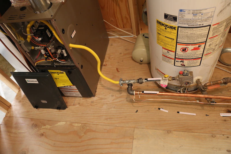
Unconventional installation of the fuel supply pipes, materials, components, valves, and support at the furnace and water heater tank.
SEDIMENT TRAP
A sediment trap must be installed downstream of the gas shutoff valve as close to the furnace as possible. The trap could be a simple tee fitting with a nipple of any length and a cap.
Observation
There is not a sediment trap installed. Defect.
APPLIANCE SHUTOFF VALVES
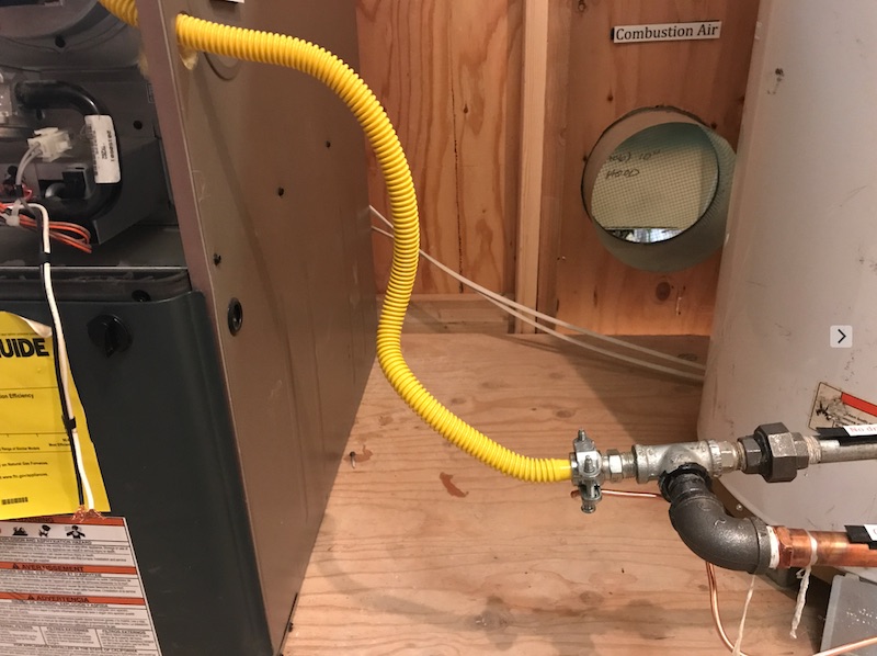
Shutoff valves must not be installed in concealed locations and furnace plenums. Shutoff valves must be accessible, located in the same room as the appliance, and protected from damage. The shutoff valve must be within 6 feet of the appliance. It must be located upstream of the union or connector device.
Observation
There is no shutoff valve installed.
FLEXIBLE GAS CONNECTORS vs. CSST
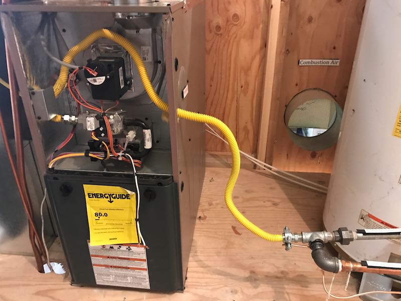
- Corrugated Stainless Steel Tubing (CSST) is observed in the garage and under the deck.
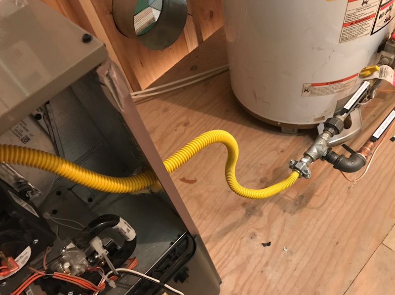
- There is a flexible connector at the HVAC equipment in the furnace room.
CSST should not be confused with natural gas appliance flexible connectors. Flexible connectors are used to attach moveable appliances to the gas piping system. CSST is typically routed beneath, through or alongside floor joists in the basement, inside interior wall cavities and on top of ceiling joists in attic spaces.
CSST piping systems must be installed in accordance with the terms of their approval, the conditions of listing, the manufacturer’s instructions, and the IRC.
CSST is a flexible, stainless steel pipe used to supply natural gas and propane in residential and commercial buildings. It is often coated with a yellow or black plastic coating. CSST should not be confused with flexible gas appliance connectors that join an appliance to the gas supply line of a house.
CSST is safe when properly installed.
For more information about CSST, please refer to the Plumbing Inspection Guide.
Observation
The flexible gas line should not be installed within the furnace cabinet. Only solid gas piping should be connected to and installed within the cabinet.
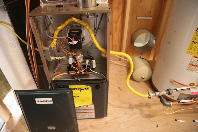
Observation
The flexible gas line is extremely bent within the cabinet and is possibly damaged, but his flexible line should not be installed within the cabinet.
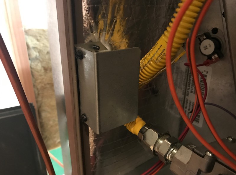
APPLIANCE CONNECTIONS
Appliance fuel connectors should be installed according to the manufacturer's recommendations and code. The total length of a connector should not be greater than 6 feet.
A union fitting must be installed for appliances connected by a rigid metallic pipe.
Observation
There is not a union fitting installed.
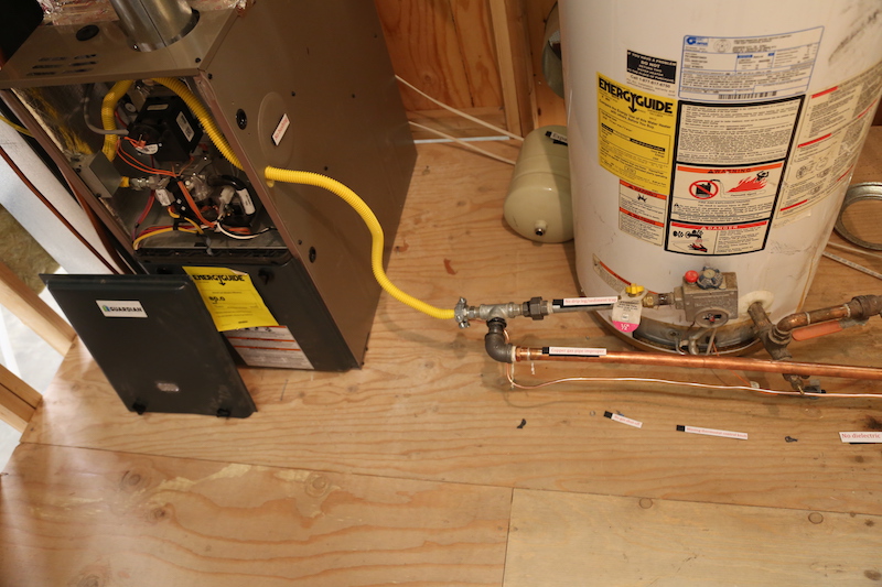
PIPING SUPPORTS
Piping must be supported at intervals no less than 6 feet.
Observation
There is inadequate support for the fuel pipes.

VENTS
Type B vents are designed for venting non-condensing gas appliances equipped with a draft hood or fan-assisted appliances with a non-positive vent pressure.
Type BW vents are for gas-fired wall furnaces. They are oval shaped to be fitted into a wall cavity.
Type L vents are for oil-burning appliances.
Type B and BW are double-walled and air-insulated vent pipe systems with aluminum inner walls and galvanized steel outer pipe walls.
Observation
The gas vent pipe from the water heater tank is improperly sloped. There is a disconnection at the elbow. This vent pipe is connected to the shared vent stack with the furnace.

Cloth duct tape is not permitted to be installed on fuel-burning appliance vent pipes. Many municipalities do not allow metal foil tape either.

Single wall vent pipe must be connected with 3 sheet metal screws at each joint.
Single wall flue vents require a six-inch minimum of clearance to combustibles, and B-vent (double wall) requires minimum 1-inch clearance.
INSULATION SHIELD
Observation
There is no insulation shield installed in the attic around the flue vent pipe.
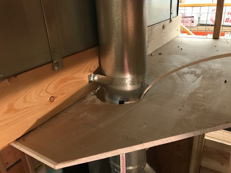
Where the vent passes through insulation in an attic, the insulation shield must be terminate at least 2 inches above the insulation and must be secured in place.
FIREBLOCKING & CLEARANCE
Observation
Electrical cable is in contact with the vent pipe of the furnace.
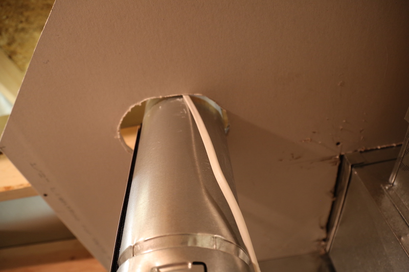
Observation
Missing fireblocking at the furnace vent chimney pipe where it penetrates the ceiling of the furnace room.
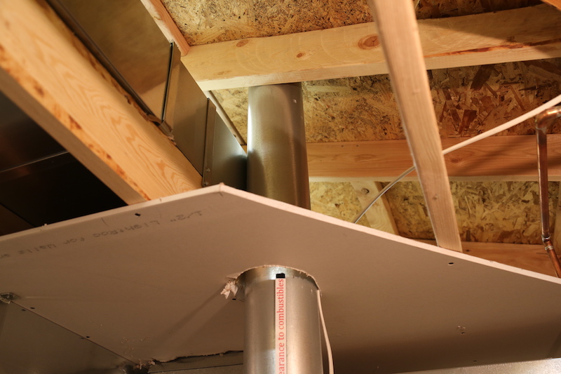
Observation
Inadequate clearance from combustibles at the gas vent stack for the furnace at the drywall and wooden structural components.
The clearance between gas vents and combustible materials is listed by the manufacturer, but is typically 1 inch for Type B.

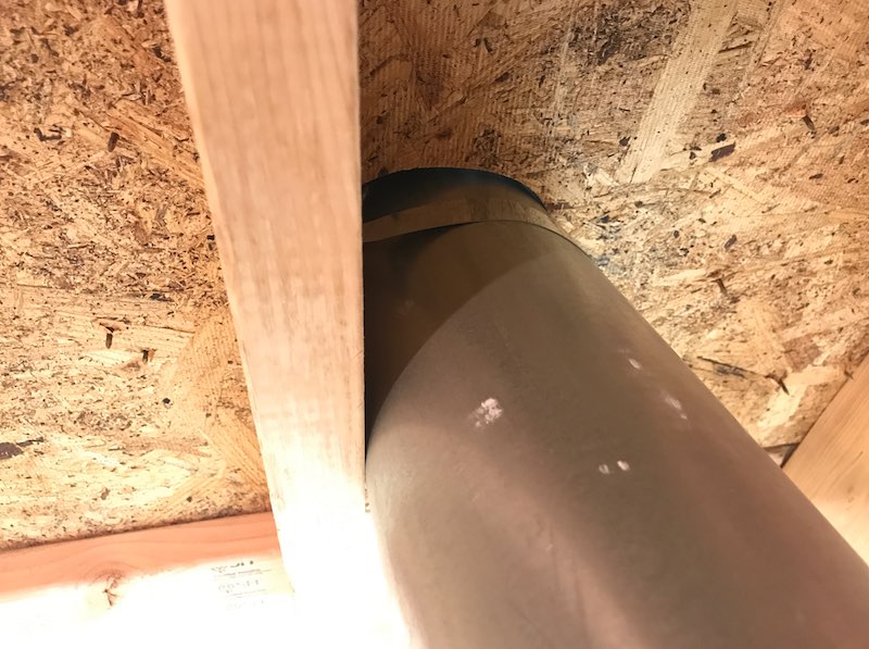
Openings around vents, chimneys, pipes, ducts, wires, and cables at the ceiling and floor levels must be fireblocked with an approved material to resist the free passage of flames and combustion products.
CHIMNEY TERMINATION
Observation
The gas vent violates the required clearance from the nearly vertical obstruction.
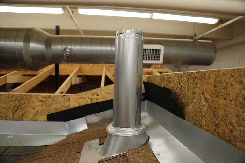
Observation
There is a missing vent cap at the furnace gas vent (chimney).

The gas vent (chimney for the furnace) should extend at least 3 feet above the highest point where it passes through a roof and at least 2 feet higher than any portion of the house within a horizontal distance of 10 feet.
Gas vents that are less than 12 inches in diameter and not closer than 8 feet from a vertical wall or similar obstruction must terminate at least 1 foot above the roof that has a slope from 0:12 to 6:12. The gas vent must have a listed cap.
DUCTS
Duct systems for HVAC equipment are installed in accordance with the ACCA Manual D, the manufacturer, or other approved methods.
Observation
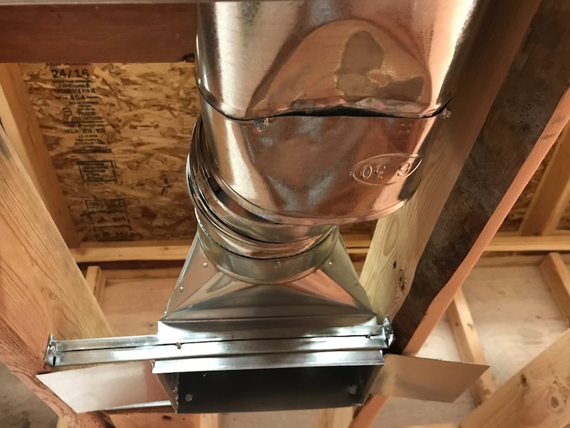
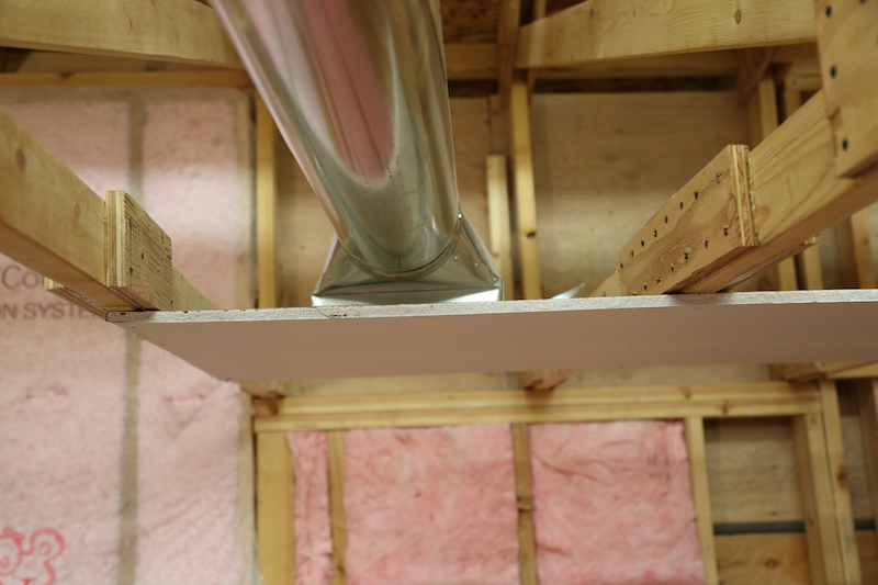
The opening between the duct and the floor sheathing creates an opening to the unconditioned crawlspace.

Observation
There is a crushed and damaged duct pipe in the ceiling of the kitchen.
Observation
Observation
Observation
Observation
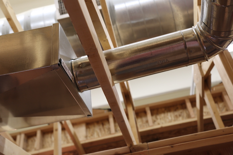
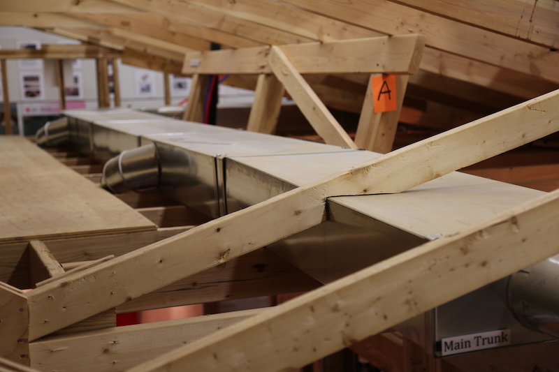
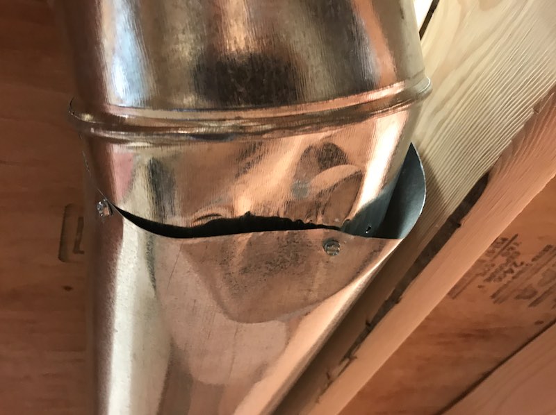
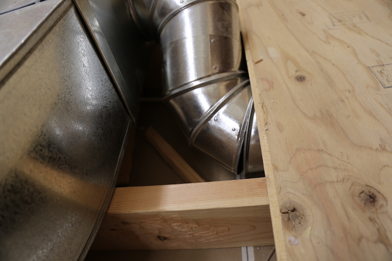
The round duct pipe in the ceiling is not sized correctly, and there is a large opening and loose connection.
Observation
Observation
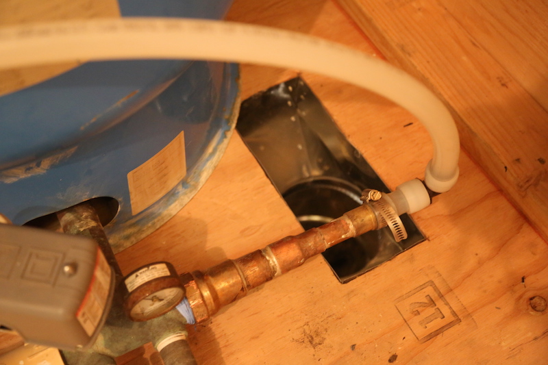
There is loose connection at the duct to the right of the water heater tank.
Observation
FASTENED, SEALED AND SUPPORTED DUCTS
Observation
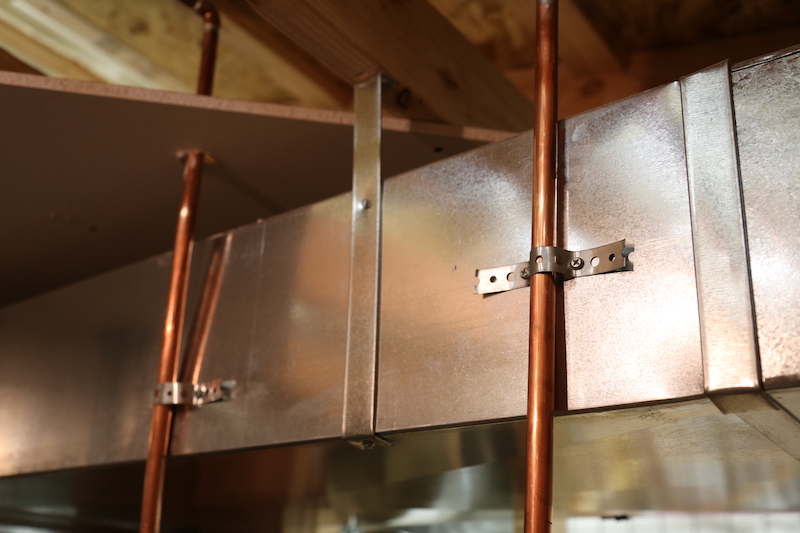
Duct should not be used for supporting pipes.
Observation
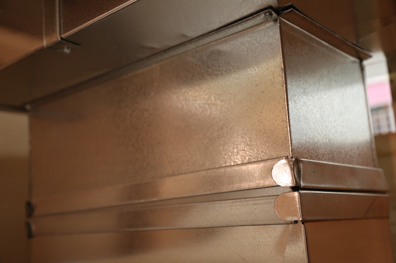
Ducts are not air sealed.
Observation
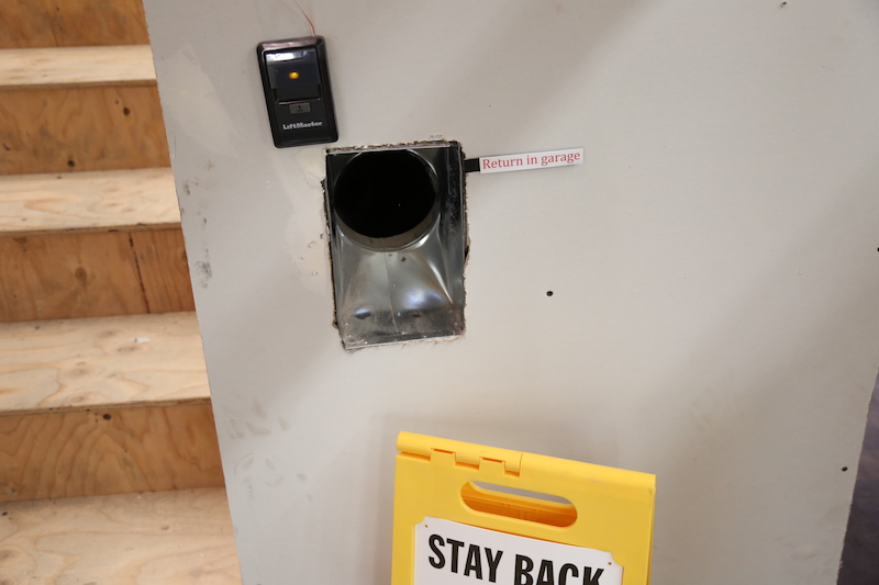
There is an open HVAC duct located on the rear wall of the garage.
According to the International Residential Code 2015 M1601.6 Independent Garage HVAC Systems, furnaces or air-handling systems that supply air to living spaces shall not supply air to or return air from a garage. Circulation of air contaminated with objectionable odors, flumes or flammable vapors is prohibited because of potential health and safety hazards.
Observation
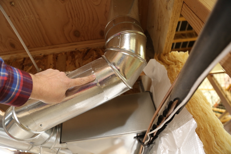
There is metal duct in the crawlspace that is not securely fastened. There are sections of duct that are loose to the touch.
Observation
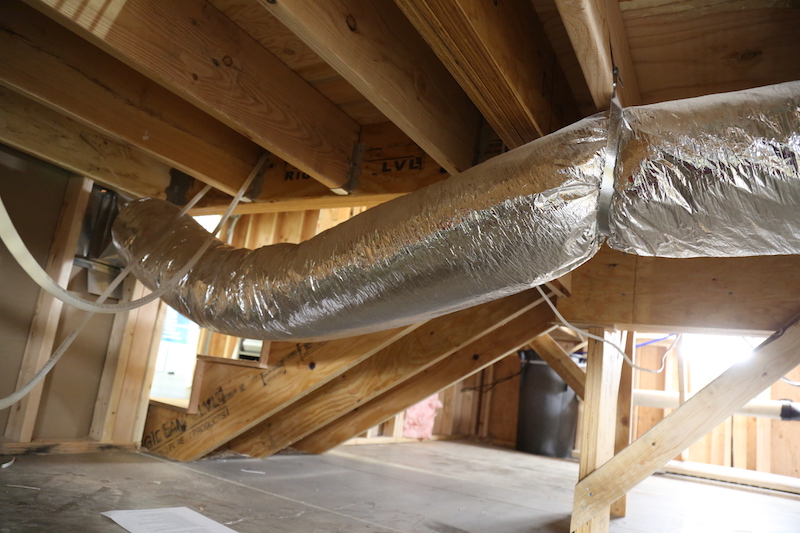
The flexible duct in the crawlspace is not supported adequately.
Observation
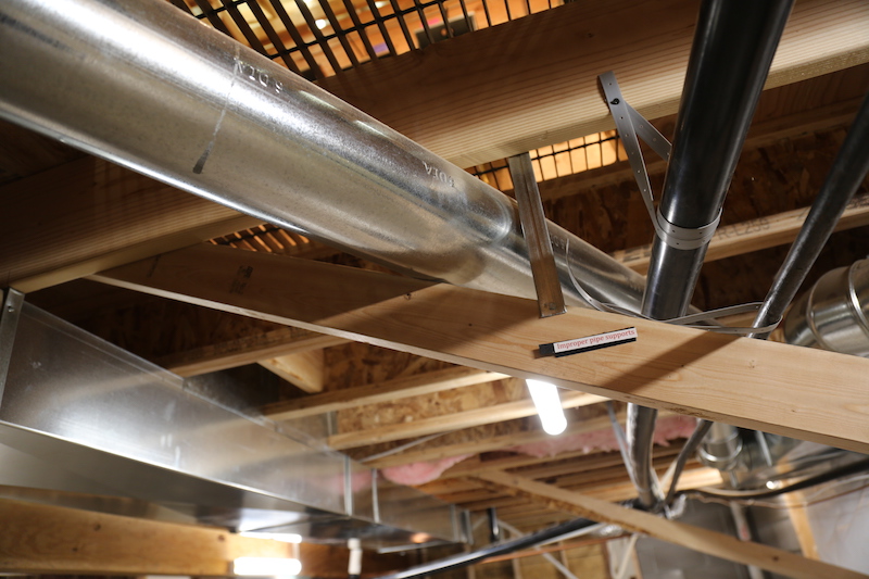
The metal duct in the crawlspace is not supported improperly, and it does not seem reliable.
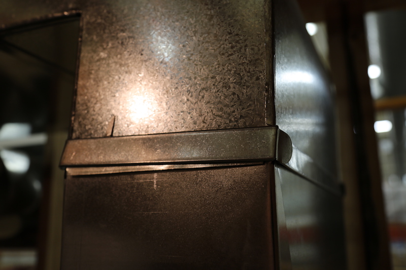
The joints, seams and connections in metallic and non-metalllic ducts must be securerly fastened and sealed with welds, gaskets, mastics, liquid sealants, or tapes. Tapes and mastics should be listed and marked with "UL 181 A-P" for tape, "181 A-M" for mastic or "181 A-H" for heat-sensitive tape.
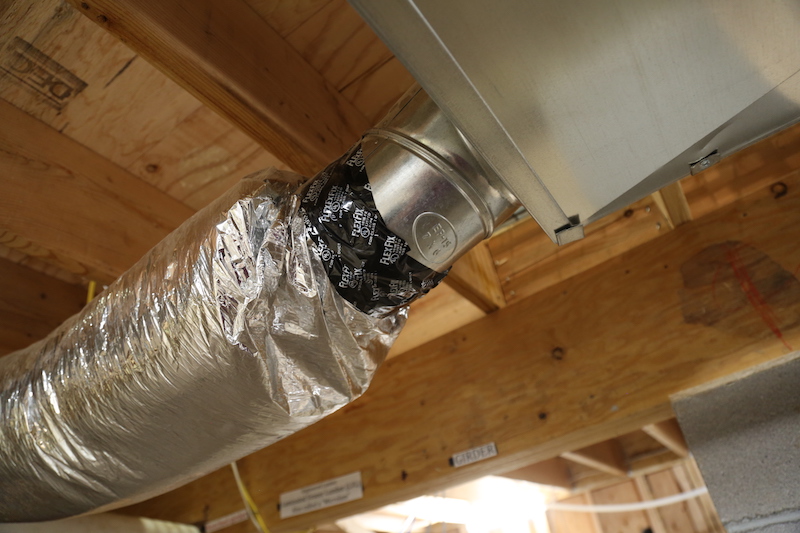
"181 B-FX" is for flexible ducts. Crimp joints for round metallic jucts should have a 1-inch lap and at least 3 sheet-metal screws or rivets at the joint.
Ducts require adequate support at regular intervals.
DUCT INSULATION
Observation
The ducts in unconditioned spaces, including the crawlspace and attic, are not insulated.
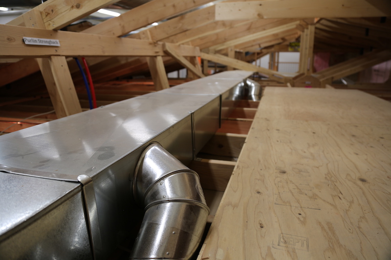
The HVAC ductwork, including supply and return, located in unconditioned spaces, including the attic and crawlspaces, should be insulated with at least an R-8. Ductwork located completely within the building thermal envelope is not required to be insulated.
Duct insulation should not pass through an opening in a ceiling, floor or wall that is fireblocked.
VIBRATION
Observation
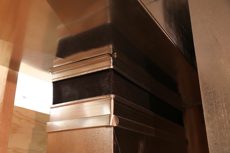
The vibration material observed above the furnace is stretched tightly without any room for movement and flexibility.
Observation
The vibration material observed from the attic space should not be located there. This vibration material should be accessible for easy inspection and service, if needed. The vibration material is very tight and has no material for flexibility.
CLEARANCE
Observation
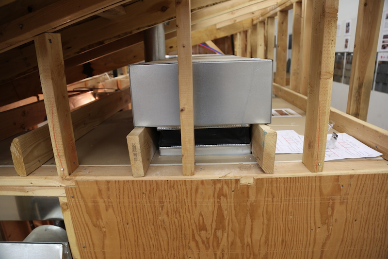
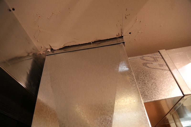
Clearances for supply plenum and ducts to combustible materials are in accordance to manufacturer's instructions and typically apply within 3' of central heating furnace. Typical clearance where applicable is one inch.
RETURN AIR OPENINGS
Observation
There should not be a return duct register installed in the kitchen.
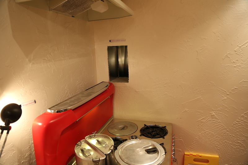
There is an exception at 2017 IRC M1602.2 where there's at least 10 feet of clearance from a cooking appliance and the opening serves the kitchen only.
Observation
There should not be a return duct register installed in the furnace room, particularly when there's competition for air with the clothes dryer and natural-draft water heater tank. Hazardous back-drafting could result.
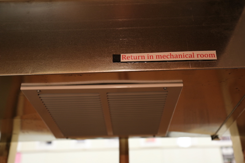
Observation
The return register at the duct to the left of the furnace and at the ceiling is within 10 feet of the draft hood of the water heater tank located in the same space as the return register.
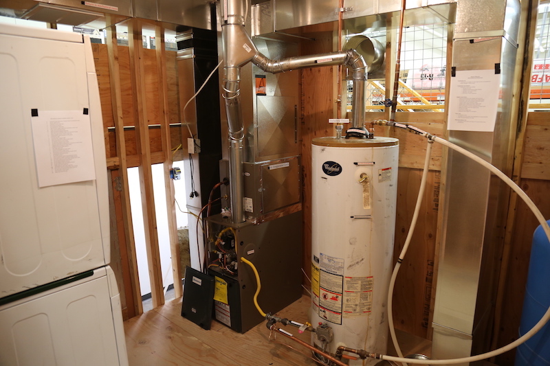
Return air openings should be located at least 10 feet in any direction from a combustion chamber or draft hood on an fuel-burning appliance in the same room.
The return air must not be taken from a kitchen, bathroom, closet, garage, mechanical room, boiler room, furnace room, or unconditioned attic space.
BUILDING CAVITIES
Nearly all building codes restrict the use of cavity spaces as supply ducts. However, it has been common practice to use cavity spaces as return-air pathways. Building cavities used as return-air plenums is one of the leading causes of duct leakage in homes today.
Still commonly used is the panned floor joist. Using floor joists as return ducts by panning can cause leakage because negative pressure in the cavity will draw air from the outside into the cavity through the construction joints of the rim area at the end of the joist cavity.
Cavities (or interstitial spaces) within walls are also sometimes used as supply- or return-air pathways. These cavities often create a connection of inside air with outside air from an attic or crawlspace. It is very difficult to make such cavity spaces airtight. When cavity spaces are used as return-air pathways or supply-air ducts, a few issues will arise.
Observation
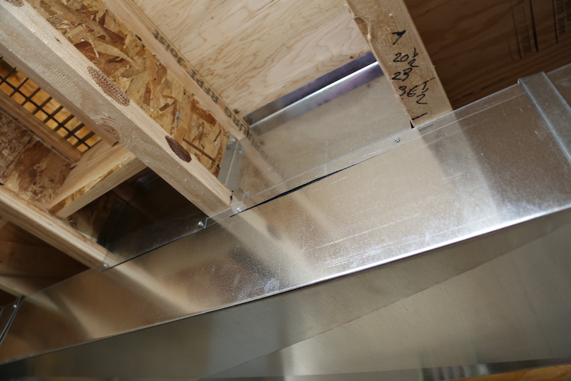
CONTROLS
2015 IRC N1103 requires a programmable thermostat to be installed for the primary heating and cooling system.
The thermostat should be located in a central living room location to make the system run effectively.
Observation
The thermostat is located in the kitchen, which is an improper location.
Observation
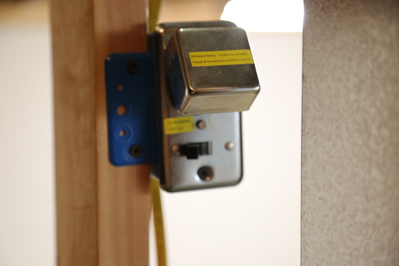
The electrical shutoff switch for the furnace has a fuse device. Fuses are antiquated.
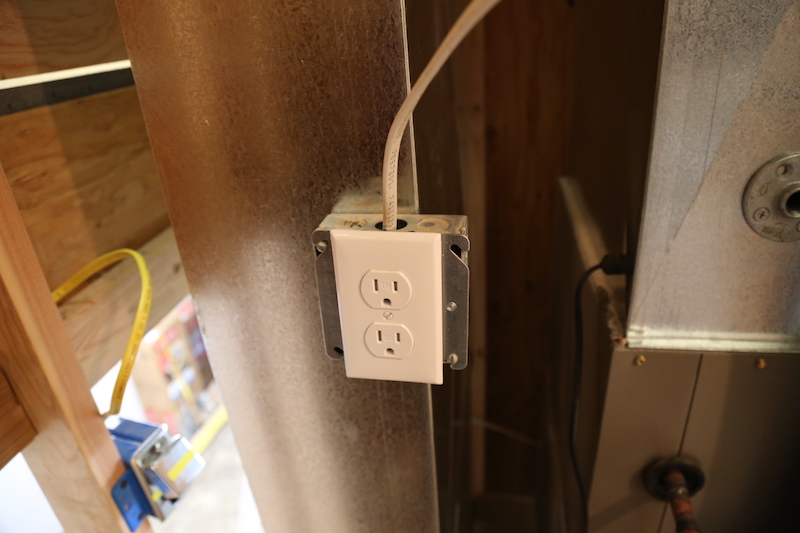
Observation
The electric receptacle is missing a clamp at the top of the electrical box.
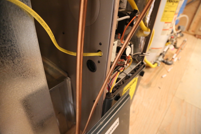
Observation
The electric wiring to the furnace cabinet is not properly installed, loose and not secure, and is missing a clamp connection to the cabinet.
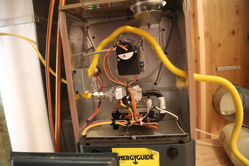
Observation
There is a loose wire connection at the controls of the furnace, near the burner control component.
AIR FILTERING
FILTER ACCESS
The air filter should be accessible for inspection and service.
Observation
The air filter is not accessible. The refrigerant lines block the filter access location.
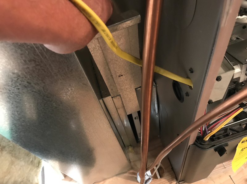
AIR CONDITIONING
CONDENSATE
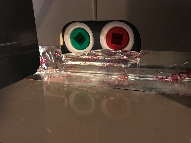
Observation
The condensate drain lines and condensate pump are not installed.
SUPPORT
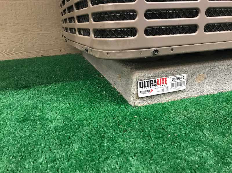
Observation
The unit appears to be off-center of its support base.
CLEARANCE
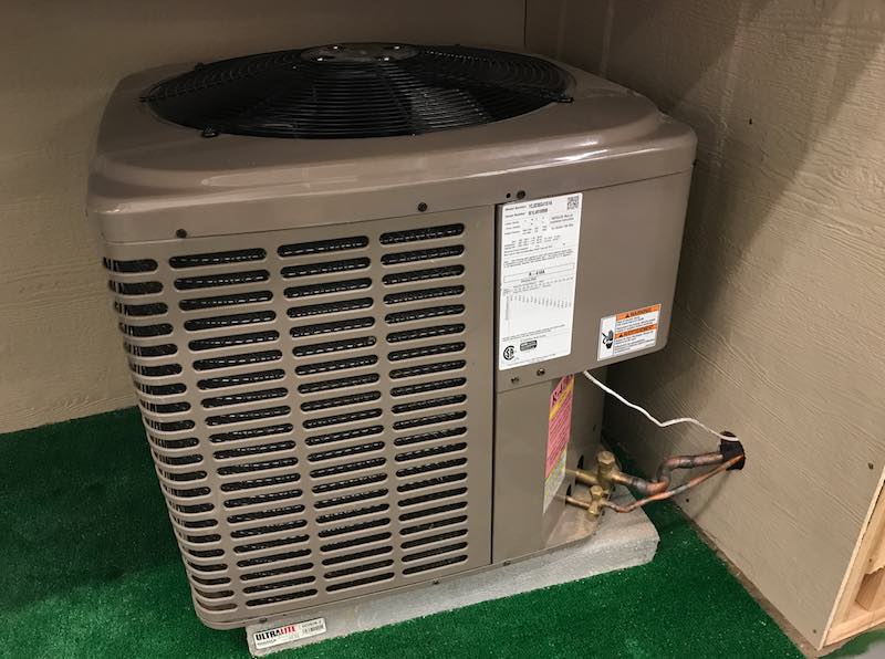
Observation
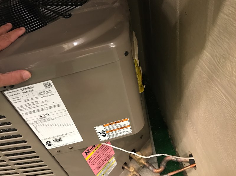
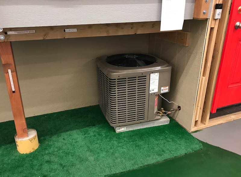
Inadequate clearance between the air conditioner's outdoor compressor unit and the house and deck structures.
REFRIGERANT LINES
Observation
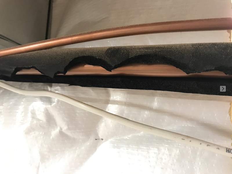
The pipes for the refrigerant vapor (suction) line should be insulated with at least an R-4 value.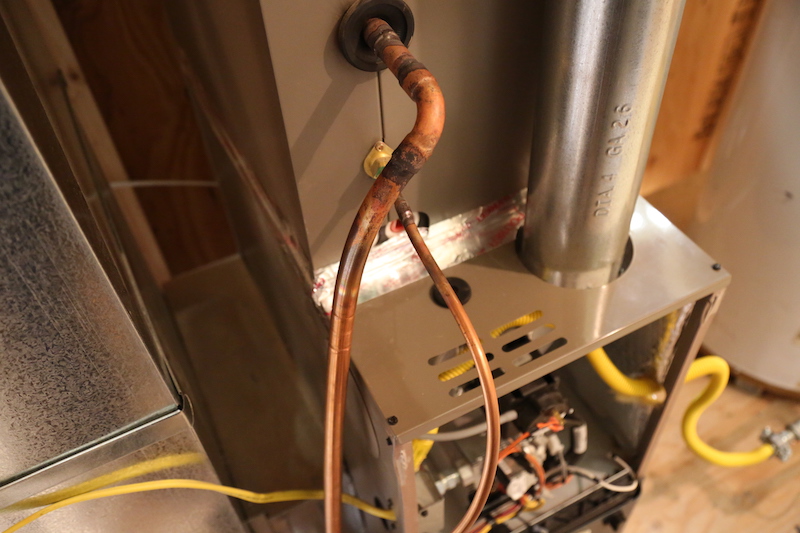
Observation
The refrigerant lines are improperly attached to and supported by the ductwork.

Observation
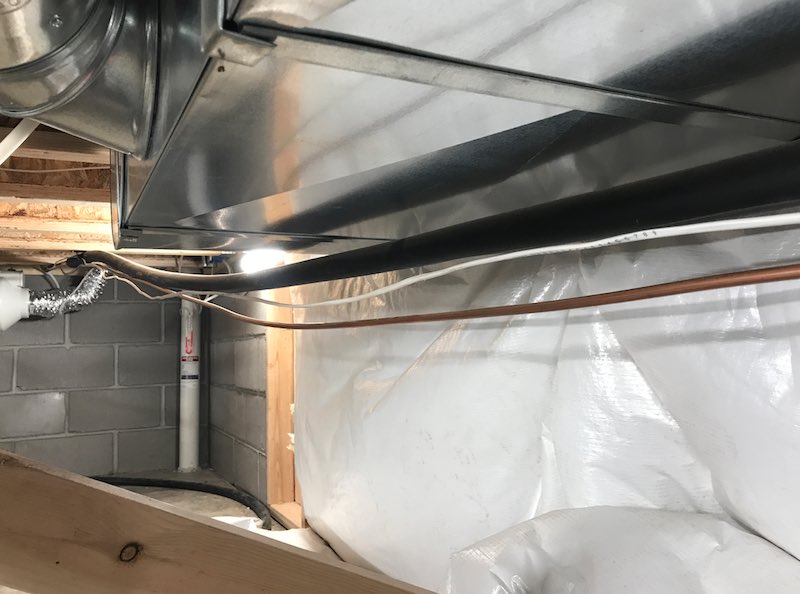
The refrigerant lines in the crawlspace are inadequately supported. They are hanging.
Observation
There is a large open hole in the siding through which the refrigerant lines pass. This hole should be sealed to prevent vermin entry and moisture intrusion. 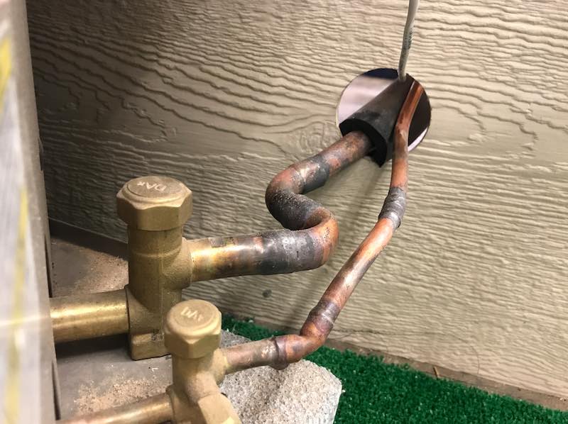
Observation
There's a squeezed, damaged area of the refrigerant line located near the air filter of the furnace. 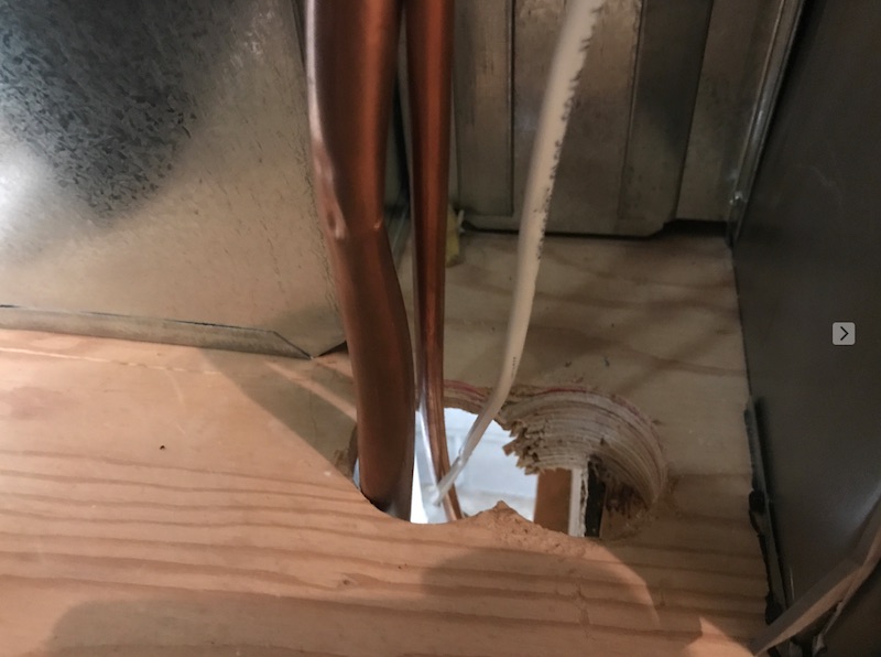
Observation
There's no slack in the refrigerant lines.

Observation
There are sections of pipe foam insulation on the suction line. There are damaged insulation in areas.
ELECTRICAL
Observation
The electrical disconnect is missing. According to NEC 440.14, there should be a electrical disconnect within sight and readily accessible of the air conditioning unit.
Observation
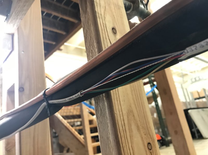
The low-voltage line for the air conditioner system is damaged as observed from the crawlspace.
Observation
There should be an GFCI-protected electric receptacle installed located within 25 feet of the air conditioner outdoor unit and on the same level as the equipment.
There is no exterior receptacle properly installed.
