Standards of Practice
The International Standards of Practice for inspecting the electrical system is located at www.nachi.org/sop.
Free, Online Course
To learn more, take InterNACHI's free, online How to Perform Residential Electrical Inspections Course.
Weatherhead
Observation

Not minimum 13' height (NEC) above floor.
Observation

No bushing (phenolic insulator).
Observation

Inadequate drip loop.
Observation

Improper splices.
Illegal line-side tap (inside soffit).
Mast
Observation

Inadequate attachment to wall.
Observation
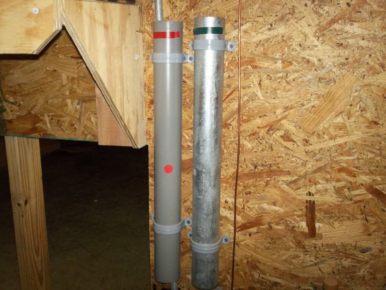
The mast is electrical metallic tubing (EMT) which is NOT an acceptable material. The mast should be of:
-
Intermediate metal conduit (IMC); or
- Galvanized rigid conduit (GRC). Samples of each are attached to the wall.
Meter
Observation
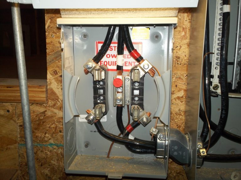
The amperage rating of the 3/0 (225-amp) copper service entrance conductors exceeds the amperage rating of the electric meter socket enclosure (135 amps) as viewed on the meter label.
Observation

The bonding bushing conductor is in contact with phase lug.
Note:
Also attached to the wall is a section of polyvinyl chloride (PVC) conduit that is NOT acceptable as electrical mast material.
Electrical Panels-Panel #1 (Service Panel)
Observation

Description: GE 200-amp Main Breaker Panel with a 200-amp main disconnect (no other breakers).
Observation

Observation

Panel/components are not connected to a service grounding system (SGS) SGSs include:
- Grounding electrode conductor (GEC);
- Grounding electrode (examples: driven rod(s), concrete encased, grounding ring/plate, water pipe where acceptable).
Observation
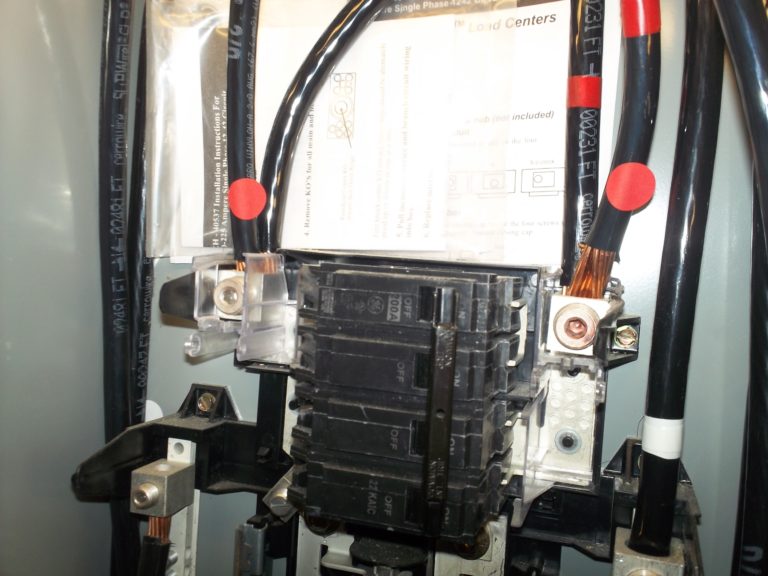
Main lugs are double tapped to feed panel #2.
Observation
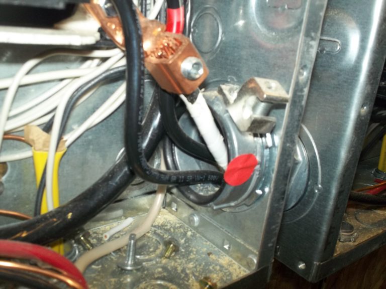
Panel/components are not connected to a service grounding system (SGS).
Distribution (sub-) Panel
Observation
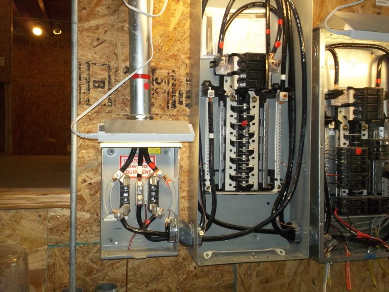
The 200-amp service panel is inadequate for feeding the 200-amp.
Observation
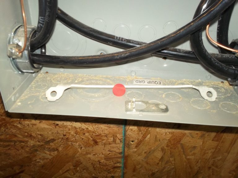
Observation
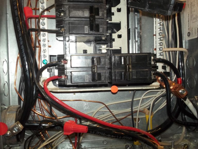
A main bonding jumper connecting the neutral and grounding bus bars should be installed in the service panel only (point of first disconnect).
Observation

No conductors attached to bonding bushings.
Observation
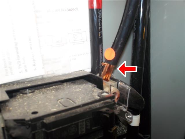
Main feed conductor over-stripped (1" max. according to label).
Observation
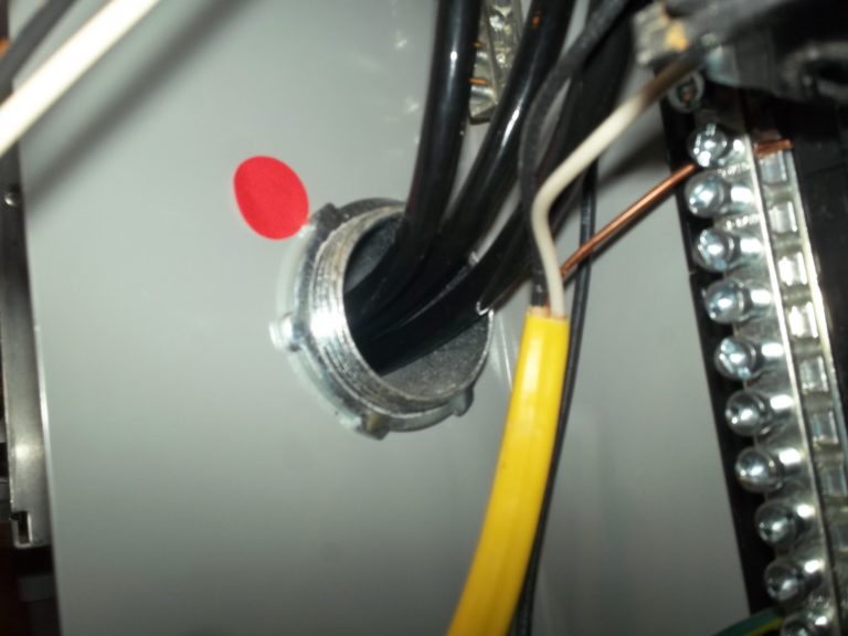
A cable connector should be installed to protect the conductor insulation from abrasion.
CONDITIONS NOT DEFECTS:
Observation
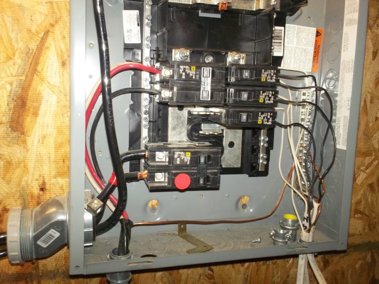
The amperage rating of the 3/0 (225-amp) copper feeders exceeds the 200-amp maximum rating of the load center.
This is acceptable as long as the amperage rating of the main disconnect does not exceed the amperage rating of load center.
Observation
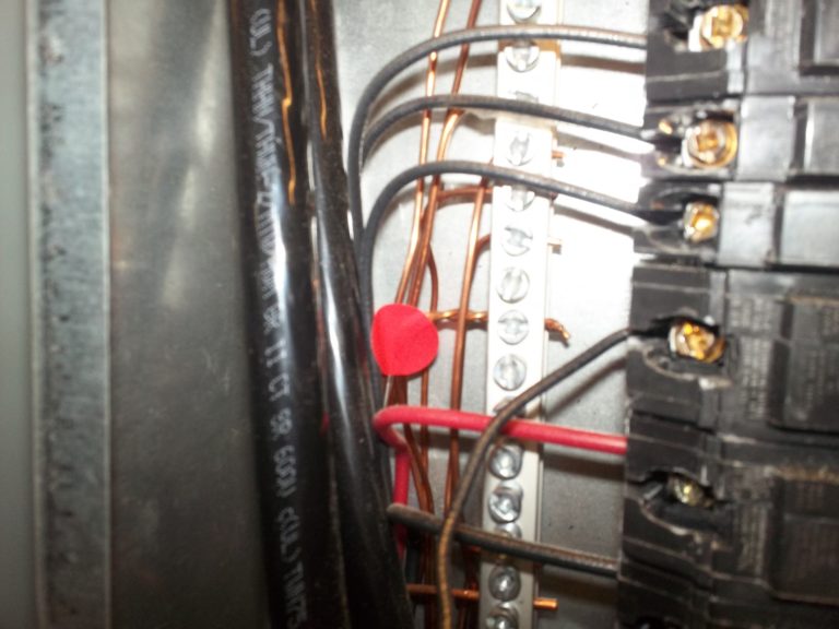
Multiple grounds under the same screw.
Observation
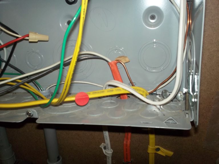
Vinyl insulation extends several inches into the panel.
Observation

Pig-tailed breaker.
Distribution (sub-) Panel
GE 100-amp Main Breaker load center with no main disconnect. Backfed by 125-amp breaker. Circuit breakers are installed.
Observation
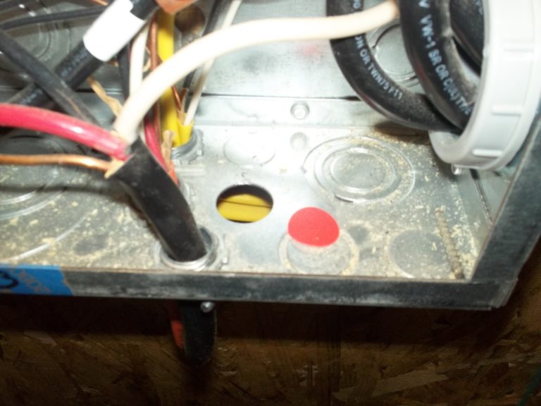
Unfilled holes.
Observation
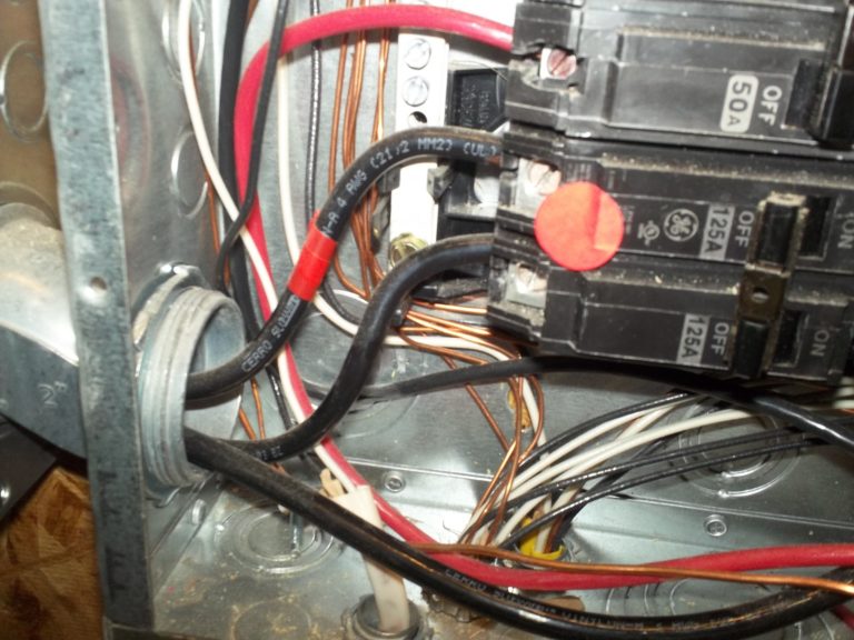
Missing cable connector.
Observation
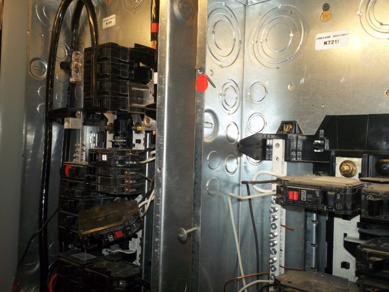
Deadfront cover attached with improper screws.
Sharp, course-thread screws can cut conductor insulation potentially causing a dangerous arc flash.
Observation
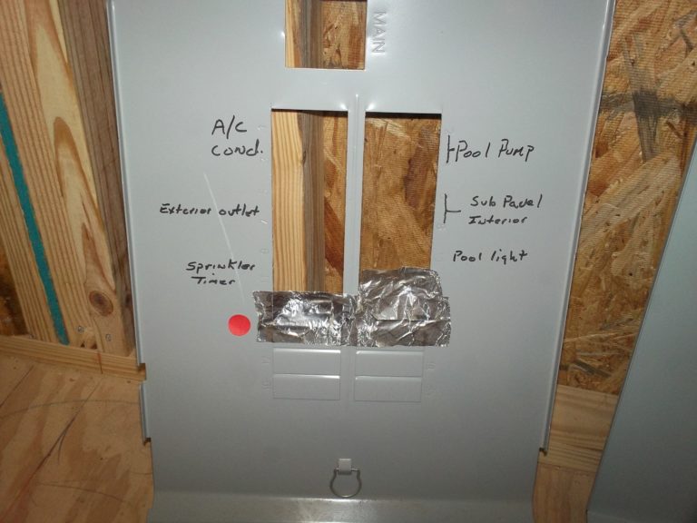
Deadfront cover missing filler plates (twistouts).
Observation
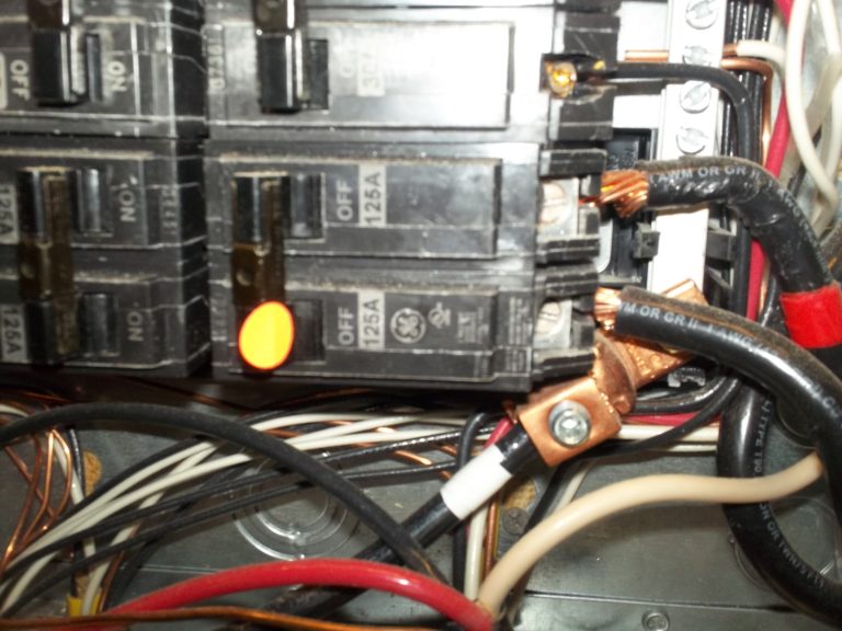
The amperage rating of the 125-amp backfeed breaker exceeds the 100-amp maximum amperage rating of both the #4 copper feeders and the load center.
The 125-amp backfeed breaker has no retaining device.
Observation
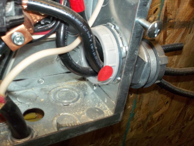
No bonding bushing.
Wherever feeders enter or leave a load center through concentric knockouts, a bonding bushing must be installed to ensure electrical continuity of the bonding/equipment grounding system. Bonding bushings should be connected to the neutral bus bar.
Observation

No insulated bushing is installed to protect feeders against abrasion where they enter the load center.
Observation

Observation

Multiple 20-amp breakers are connected to 14-gauge conductors. 20-amp breakers should be connected to 12-gauge conductors.
Observation
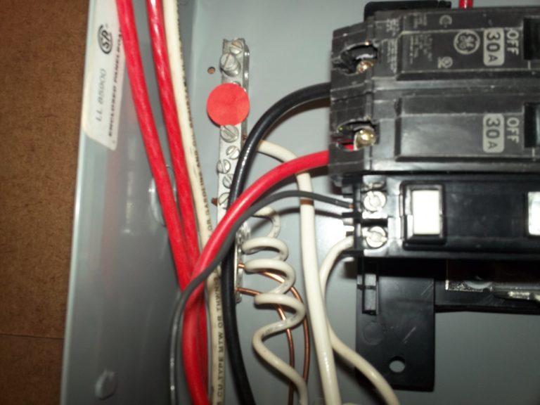
The GFCI breaker is connected to the grounding bus bar, not the neutral bus bar.
Observation
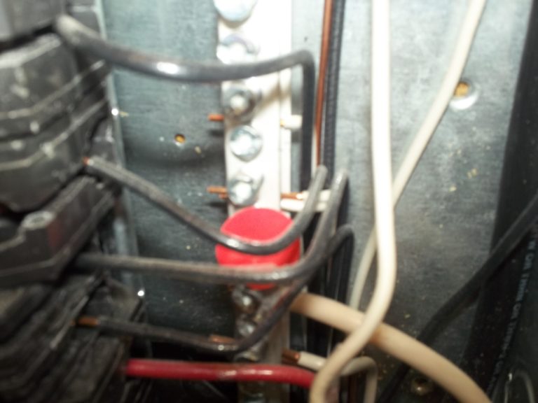
Multiple neutral conductors under the same screw in the neutral bus bar.
This is wrong because it complicates isolating the neutral for one of the circuits involved.
Observation
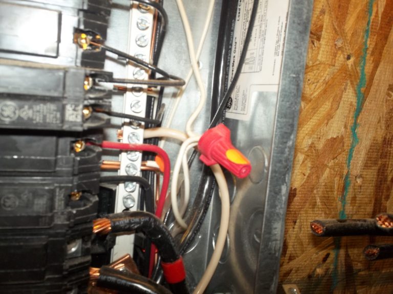
Pig-tailed neutrals.
Again, this is wrong because it complicates isolating the neutral for one of the circuits involved.
Observation
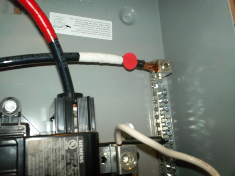
Neutral conductor.
Observation
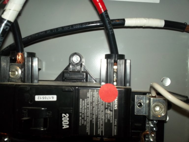
In order to complete their insertion into the 125-amp breaker (lower right corner) the #1 (150-amp) copper conductors had strands cut away.
Cutting strands reduces the amperage rating of a conductor. 37. Unfilled Knockout.
Observation
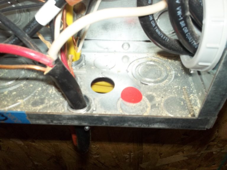
Unfilled Knockout.
Observation

Grounding conductor on the neutral bus bar.
First Detached Structure Electrical Panel
Square D 125-amp load center, backfed by 125-amp breaker.
Grounding conductors of different gauges under the same screw. The 125-amp backfeed breaker has no retaining device. Neutral and grounding bus bars are not isolated from each other.
Second Detached Structure Electrical Panel
Neutral and grounding bus bars are not isolated from each other.
Observation

Neutral and grounding bus bars are not isolated from each other.
