STANDARDS OF PRACTICE
The International Standards of Practice for inspecting the electrical system is located at www.nachi.org/sop.
GARAGE
Observation

Receptacle A1 has an external power supply cable entering behind the device cover.
Observation
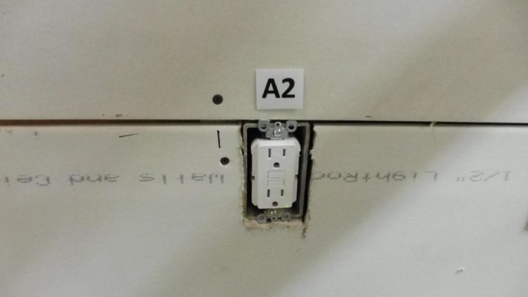
GFCI Receptacle A2 is missing cover plate.
Observation
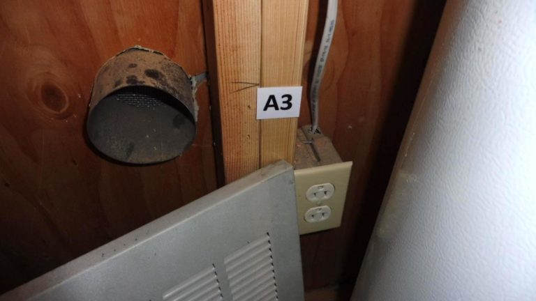
Receptacle A3 has unsecured and unprotected surface mounted conductors (above and to the right of the device). NM type wire should be protected when potential physical damage is present. (NM cable is not approved for surface installation without protection). NM Cable is not secured. Nonmetallic-sheathed cable shall be supported and secured by staples, cable ties, straps, hangars, or similar fittings designed and installed so as not to damage the cable, at intervals not exceeding 1.4m (4 1/2 ft) and within 300mm (12in.) of every outlet box, junction box, cabinet, or fitting.
GARAGE CEILING
Observation

Receptacle A1 is missing the device cover.
Observation

Item A2 (Extension cords being used to power the garage door openers). Permanent power source is recommended near the operator.
STAIRWAY
Observation
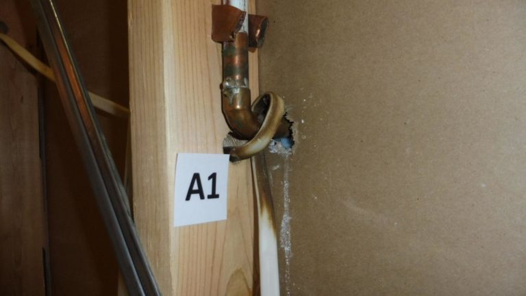
Wire A1 has (Damaged sheathing) and is wrapped around a water pipe.
Observation

Wire A2 is wrapped around plumbing pipe.
Observation
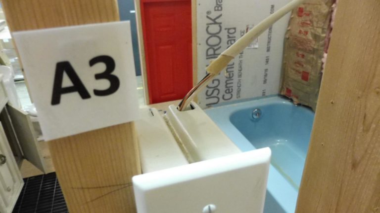
Switch A3 has exposed conductors above the electrical box. Minimum of ¼” of sheathing should enter the electrical box (stairway).
BATHROOM TUB AREA
Observation

Switch A1 has a wire cut below the electrical box. Wire is also unsecured. Switch is allowed outside of the tub footprint (not in the enclosure). Nonmetallic-sheathed cable shall be supported and secured by staples, cable ties, straps, hangars, or similar fittings designed and installed so as not to damage the cable, at intervals not exceeding 1.4m (4 1/2 ft) and within 300mm (12in.) of every outlet box, junction box, cabinet, or fitting.
Observation
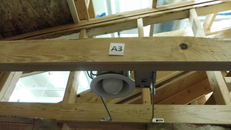
Luminaires (lighting fixtures) located in this zone shall be listed for damp locations, or listed for wet locations where subject to shower spray. The zone covers 3 feet horizontal and 8 feet vertical measured from the top edge of the tub and shower base.
BATHROOM TOILET WALL
Observation

Receptacle A1 near the toilet is not GFCI protected. (It is recommended that all electrical devices within 6’ of all water sources be GFCI protected).
NEC Section 210.8(A)(9) and (10) Bathtubs, Shower Stalls, Laundry Areas
Two new list items have been added to Section 210.8(A). The requirements for ground-fault circuit interrupter protection (GFCI) have been expanded for dwelling units. GFCI protection is now required for receptacles installed within 6 feet of a bathtub or shower stall. Note that this requirement applies to bathtubs or shower stalls, regardless of whether they are in a bathroom or not. In addition, all 125-volt (V), single-phase, 15- and 20-ampere (A) receptacles installed in laundry areas must be GFCI-protected.
BATHROOM VANITY WALL
Observation

Bathroom vanity GFCI Receptacle A1 did not trip when tested.
NEC Section 210.8(A)(9) and (10) Bathtubs, Shower Stalls, Laundry Areas
Two new list items have been added to Section 210.8(A). The requirements for ground-fault circuit interrupter protection (GFCI) have been expanded for dwelling units. GFCI protection is now required for receptacles installed within 6 feet of a bathtub or shower stall. Note that this requirement applies to bathtubs or shower stalls, regardless of whether they are in a bathroom or not. In addition, all 125-volt (V), single-phase, 15- and 20-ampere (A) receptacles installed in laundry areas must be GFCI-protected.
BATHROOM CELING
Observation

Bathroom exhaust fan A1 does not have a power source or wall switch.
ELECTRICAL ROOM EMF WALL
Observation

The GFCI Receptacle A1 near the Electrical room door has an open ground, and more than one wire entering one connector. NM type wire should be protected when potential physical damage is present. (NM cable is not approved for surface installation without protection).
Observation

NM type wire should be protected when potential physical damage is present. (NM cable is not approved for surface installation without protection).
Observation

NM type wire should be protected when potential physical damage is present. (NM cable is not approved for surface installation without protection).
Observation
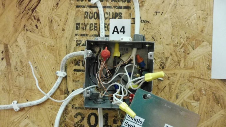
Junction box A4 on the Electrical room wall has open splices, a missing box cover, and an unterminated wire.
Observation

NM type wire should be protected when potential physical damage is present. (NM cable is not approved for surface installation without protection).
Observation

Receptacle A7 is switched (Reference Photo). NM type wire should be protected when potential physical damage is present. (NM cable is not approved for surface installation without protection).
ELECTRICAL ROOM RECEPTACLE WALL
Observation

Device A1 is a Pilot Switch controlling the overhead lights. Wires above the switch are not secured in an approved method (more than one cable under a staple and unsecured cable further above). Nonmetallic-sheathed cable shall be supported and secured by staples, cable ties, straps, hangars, or similar fittings designed and installed so as not to damage the cable, at intervals not exceeding 1.4m (4 1/2 ft) and within 300mm (12in.) of every outlet box, junction box, cabinet, or fitting.
Observation
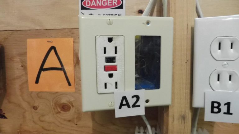
Receptacle A2 has no hot wire (black) connection and the attachment screw on the receptacle shows signs of being overheated and burnt.
Observation

Receptacle A3 has reverse Polarity (Hot wire (black) reversed with the neutral wire (white).
Observation

Receptacle A4 has the Neutral wire (white) reversed with the ground wire (bare).
Observation

Receptacle B1 is an ungrounded type receptacle.
Observation
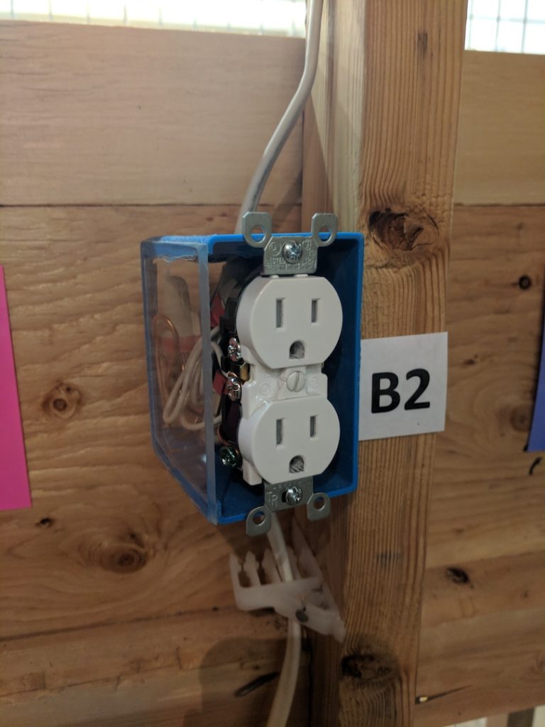
Reverse polarity, hot wire (black) is reversed with the neutral wire (white). Also missing device cover.
Observation

Reverse Polarity, Ground wire (bare) is reversed with the Hot wire (black).
Observation
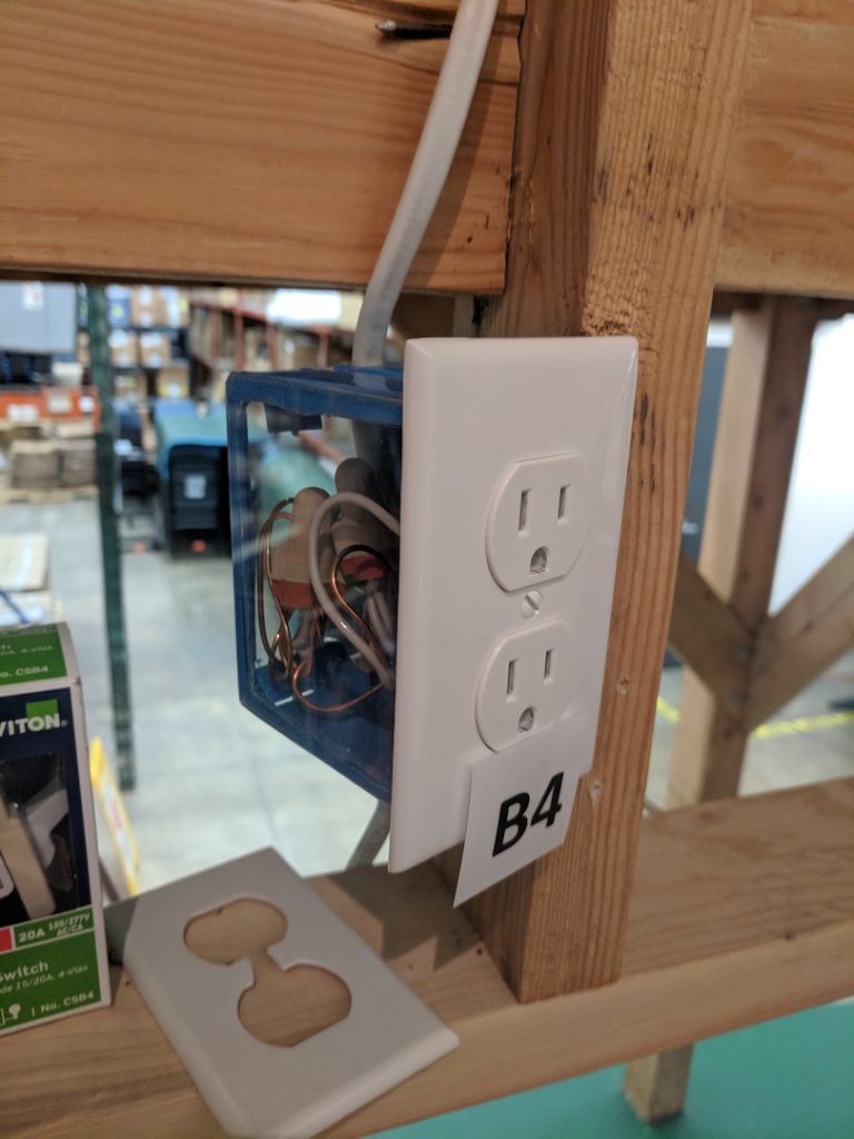
Open Neutral, white wire is disconnected from the terminal screw.
Observation

Open neutral on the bottom receptacle, the brass tab that connects the top and bottom receptacle on the neutral side is broken.
Observation
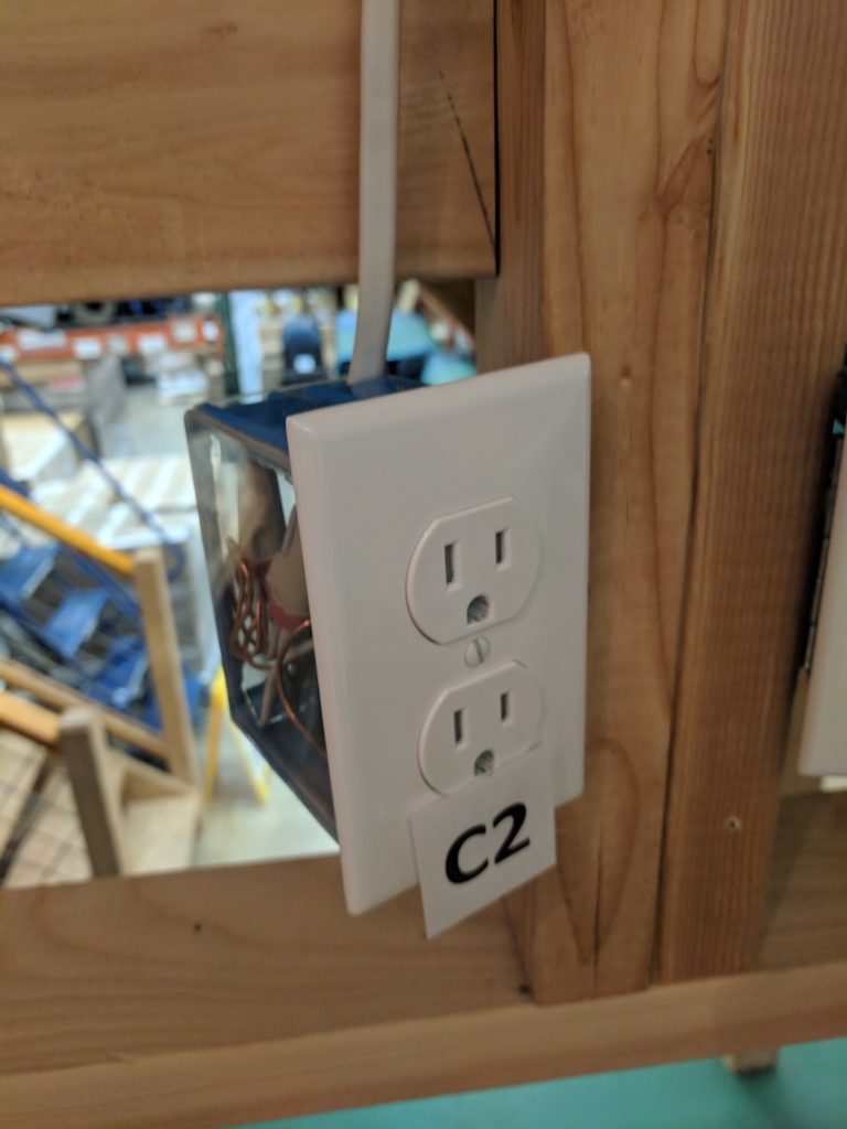
Open Ground, the Ground wire (bare) has been disconnected.
Observation
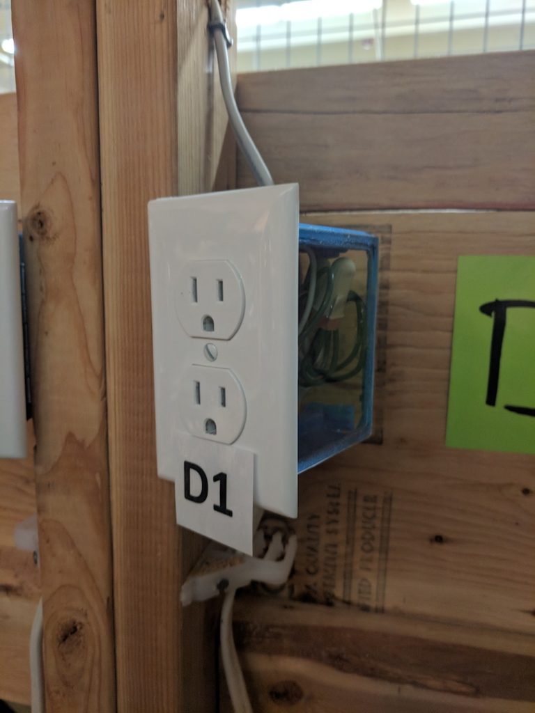
The top Receptacle is not energized, the brass tab that connects the top and bottom receptacle on the hot side is broken.
Observation
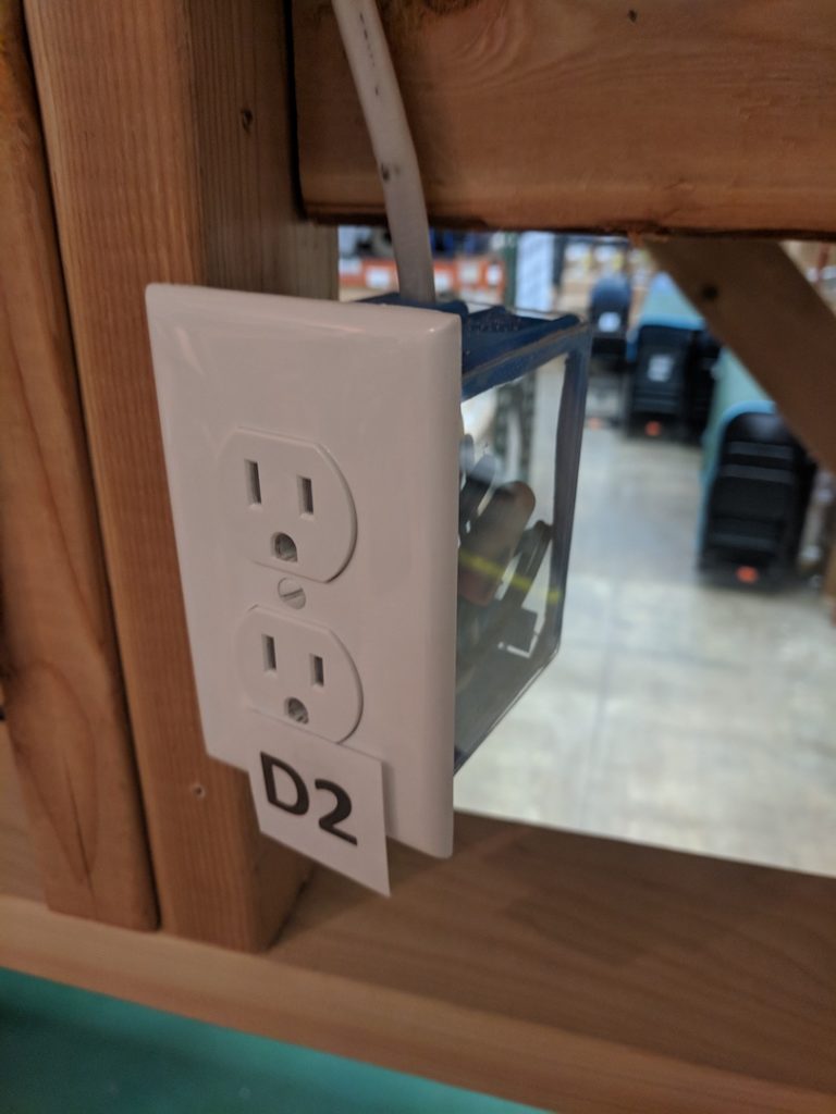
Receptacle is not energized, the hot wire (black) is disconnected.
Observation

Receptacle mounted upside down. NM Cable feeding the receptacle is not secured within 12” of the electrical box. NM Cable is located on the surface of the stud (NM Cable is required to be installed within framing members or in protective conduit if surface mounted). Nonmetallic-sheathed cable shall be supported and secured by staples, cable ties, straps, hangars, or similar fittings designed and installed so as not to damage the cable, at intervals not exceeding 1.4m (4 1/2 ft) and within 300mm (12in.) of every outlet box, junction box, cabinet, or fitting.
ELECTRICAL ROOM DOORWAY WALL
Observation

Wires above the switch are not secured in an approved method (more than one cable under a staple). The switch controls the overhead light (Light does not come on during switch operation).
Observation

GFCI receptacle does not trip when tested.
Observation
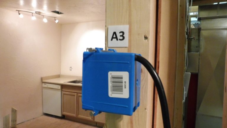
Receptacle being fed by an extension cord (Receptacle should be fed by a permanent branch circuit wire). Receptacle also missing device cover.
ELECTRICAL ROOM PANEL WALL
Observation

Main feeder wires are undersized (must be sized according to the main breaker amperage rating of 200 Amp). Main feeder wires missing Anti/Oxidant paste. Feeder wire insulation stripped to far (recommend maximum of ¼” of conductor exposed above the lug). Conductor wires have been trimmed reducing the currant carrying capacity of the feeder. Splices in the panel. Missing NM cable connector in the bottom of the panel. Arch fault breaker missing neutral conductor. Broken 20 Amp breaker. Loose double tap breaker. Sub Panel feeder (threaded offset nipple) is missing bonding bushing and ground bonding jumper wire.
Bonding at Services
NEC Section 250.92(B) is applicable to
(Bonding at services), and in part states,
“Bonding jumpers meeting the other
Requirements of this article [Article 250] shall
be used around concentric or eccentric
knockouts that are punched or otherwise
formed so as to impair the electrical
connection to ground.” For services, this
confirms that (bonding jumpers) are required
unless all concentric or eccentric knockouts
have been removed.
Observation
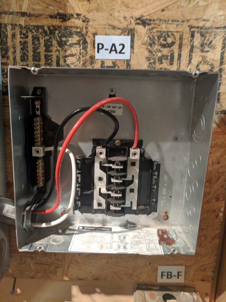
Undersized feeder wire. No grounding conductor. No isolated grounding bar. No insulated bushing on the threaded offset nipple.
Observation
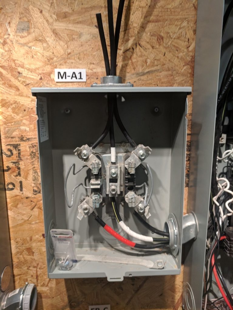
Main feeder wires are undersized (must be sized according to the main breaker amperage rating of 200 Amp). Main feeder wires missing Anti /Oxidant paste. Feeder wire insulation stripped to far (recommend maximum of ¼” of conductor exposed above the lug). Conductor wires have been trimmed or damaged reducing the currant carrying capacity of the feeder. Sub Panel feeder (threaded offset nipple) is missing bonding bushing and ground bonding jumper wire.
Observation
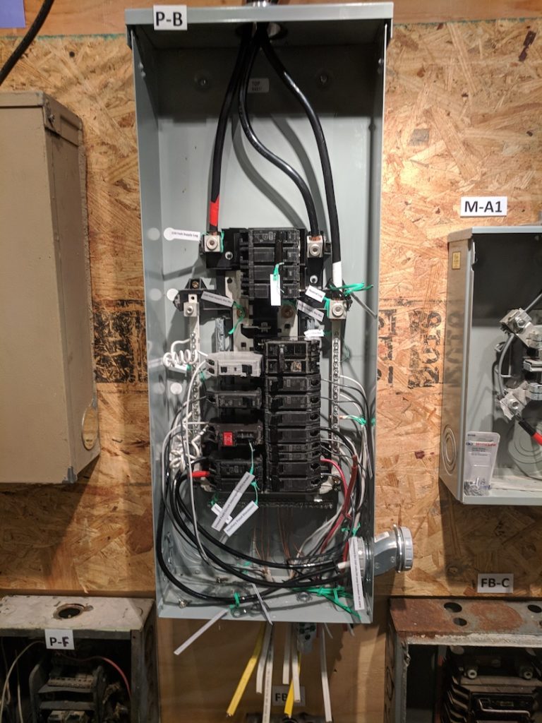
Rain Tight type rated for outdoor use. Feeder wire is undersized for the 200A main breaker. Bonding bushing is missing on the threaded offset nipple. Threaded offset nipple is missing bonding bushing and ground bonding jumper wire. Open or unused breaker slots should be covered.
Observation

Rain Tight type rated for outdoor use. Feeder wire is undersized for the 125A main breaker. Missing the correct ground termination bar. Missing inner dead front cover.
Observation

Federal Pacific Circuit breaker Panels (FPE):
Federal Pacific Electric "Stab-Lok® " service panels and breakers are a latent hazard and FPE circuit breakers can fail to trip in response to overcurrent, leading to electrical fires. The breakers may also fail to shut off internally even if the toggle is switched to "off." Some double-pole (240-Volt) FPE circuit breakers and single-pole FPE Stab-Lok® circuit breakers simply do not work safely. (The problem lies in the dissimilar materials copper to aluminum alloy used between the breaker attachment point and the main buss).
Observation
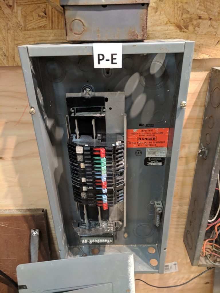
Zinsco Sylvania/Zinsco Circuit breaker panels:
While a Zinsco panel can function properly for years and even decades, as higher energy demands are placed upon a Zinsco panel they have a strong tendency to overheat. When this happens, breakers melt and are no longer capable of tripping. This leads to an extreme amount of energy surging that can’t be shut off manually, and there is a great potential for these panels to catch fire. If you have a Zinsco electrical panel It is recommended that a review by a licensed Electrical contractor be done. (The problem lies in the dissimilar materials used between the breaker attachment point and the main buss).
Observation

ITE Pushmatic / Bulldog:
There are safety warnings but conflicting opinions among inspectors and electricians about these electrical panels under either the Pushmatic™ or Bulldog™ brand names. It is apparent that Pushmatic™ or Bulldog™ brand circuit breakers, use a less reliable trip mechanism (no internal magnetic trip) than that offered by modern equipment. On this basis and pending further research we consider these products questionable with conflicting opinions that currently deserve a warning but not a condemnation.
