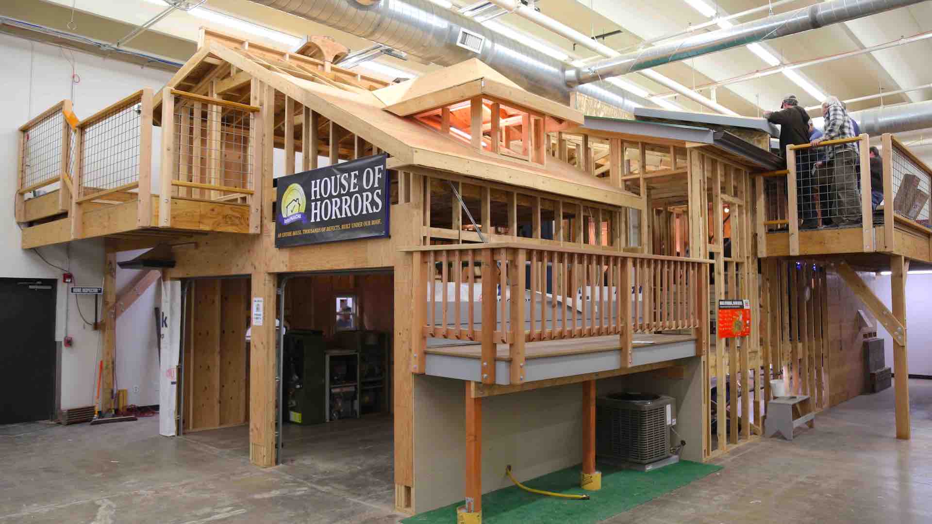
Deck Inspection Guide

OBSERVATION #1

The deck posts are off-center in relation to their footings. 

OBSERVATION #2
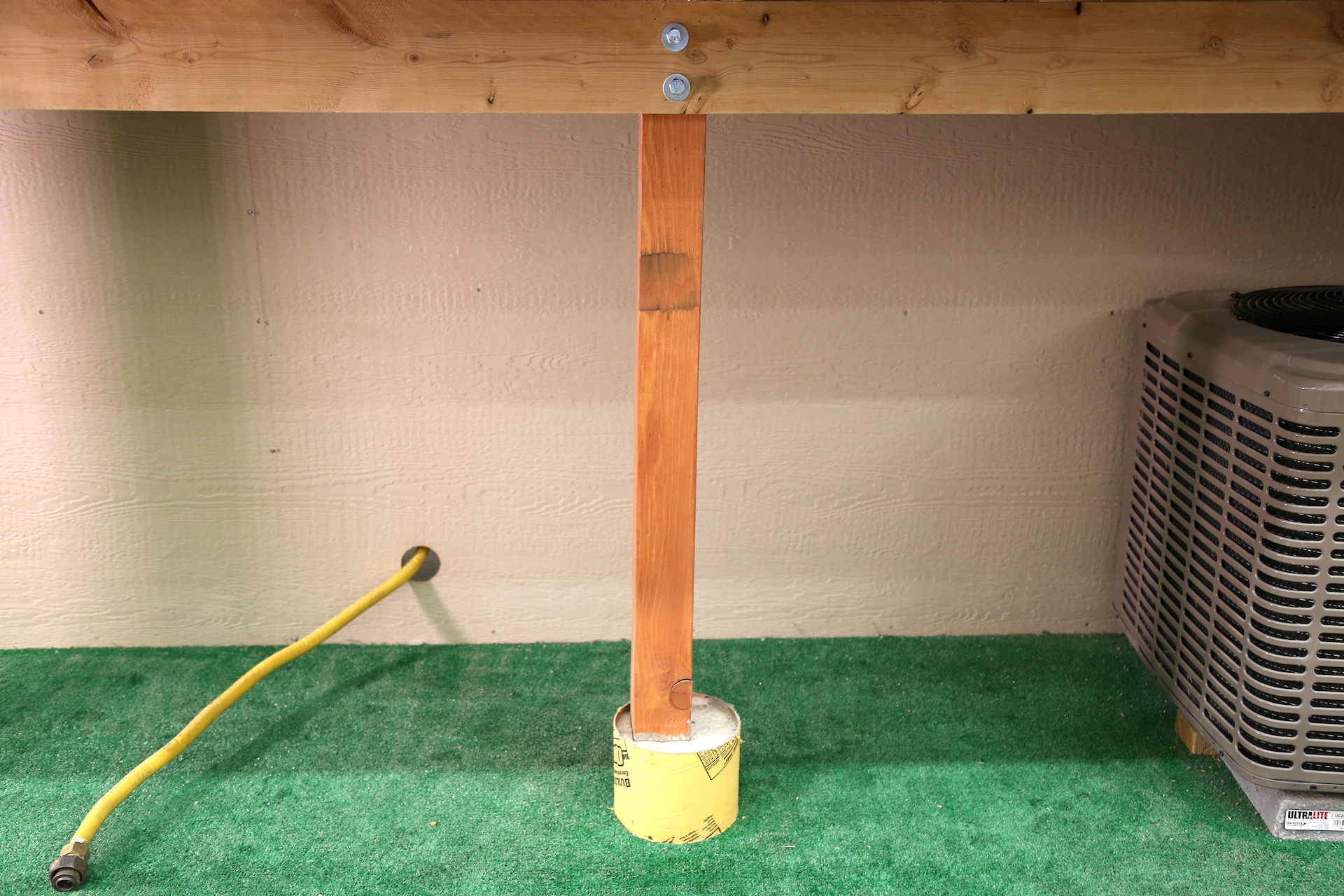
The posts are out of plumb. 

OBSERVATION #3
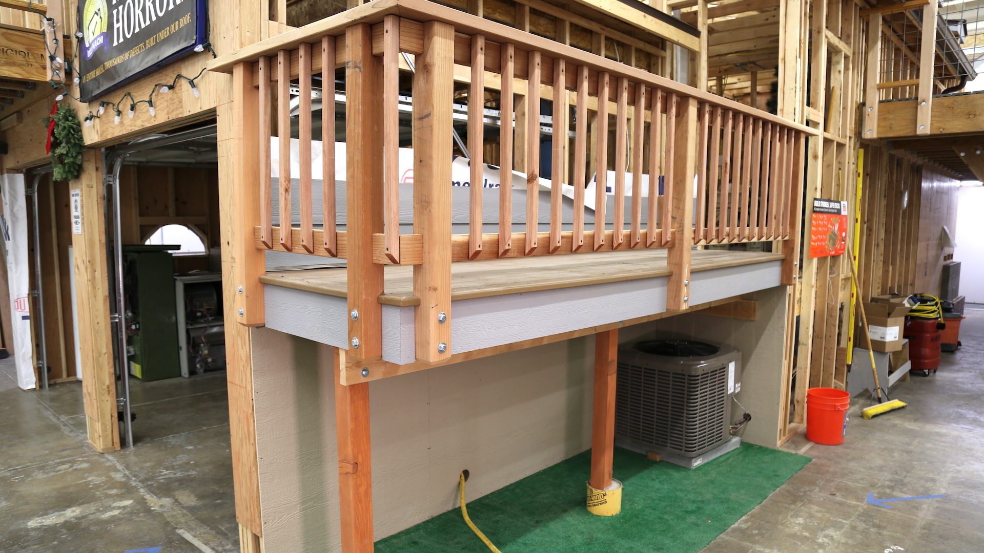
In all but the lowest of decks, deck posts should be at least 6x6, and be no higher than 12 feet; 14 feet is acceptable if cross-bracing is used.

OBSERVATION #4
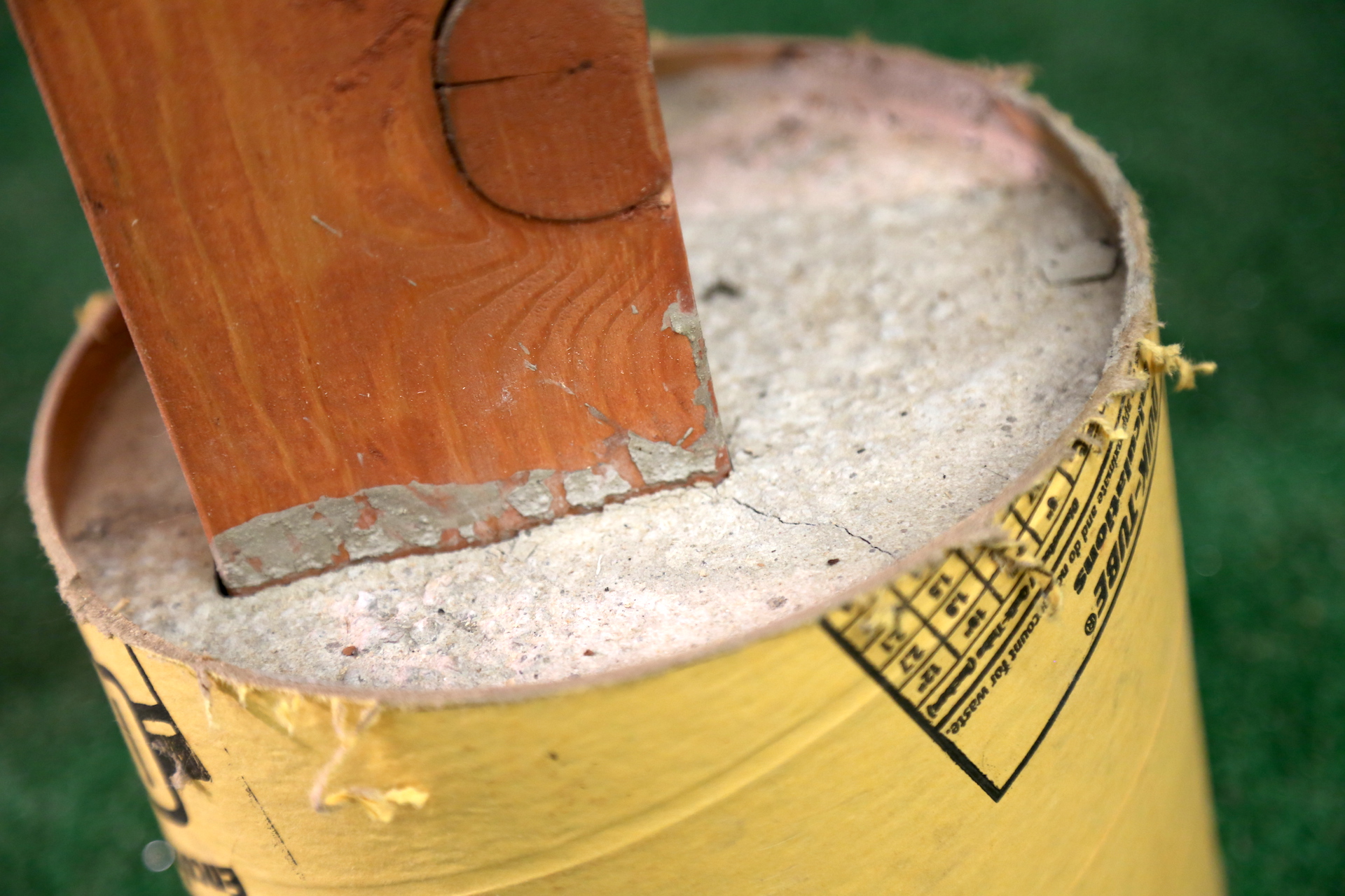
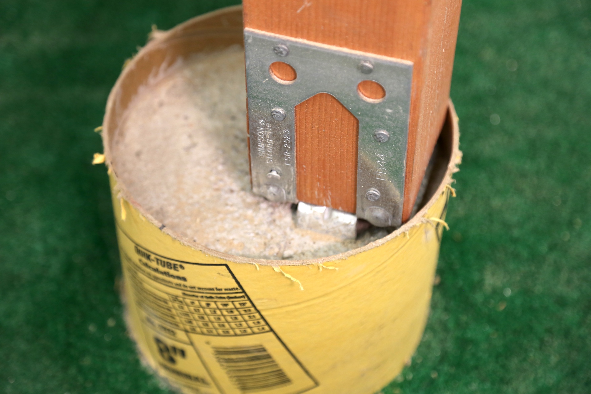
A post bottom is embedded into concrete. 

The one post is not securely attached to its footing. Posts should be connected to their footings so that the posts don't lift or slip off.

In accordance with IRC 2015 507.8.1, deck posts can bear on footings in a few different ways, including having the post bear on concrete stems, bear on a typical footing above or below grade, and bear on a concrete footing and encased in concrete.

OBSERVATION #5
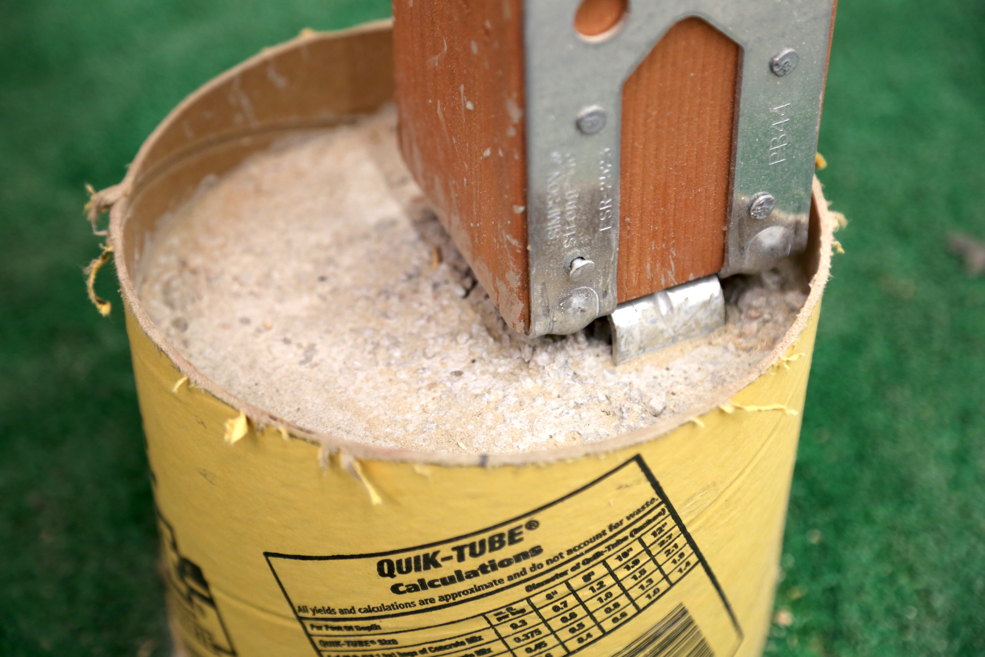
The footing tube will hold water, which may cause wood decay. 

OBSERVATION #6
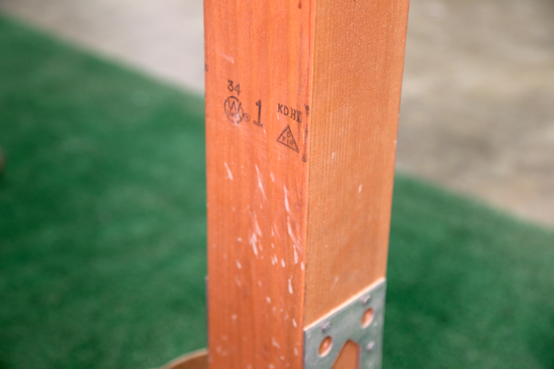
The posts are not of decay-resistant wood. See the stamp on the back of a post indicating that it is Douglas Fir.

Posts in contact with soil should be pressure-treated and oriented so the cut end is above grade.

OBSERVATION #7
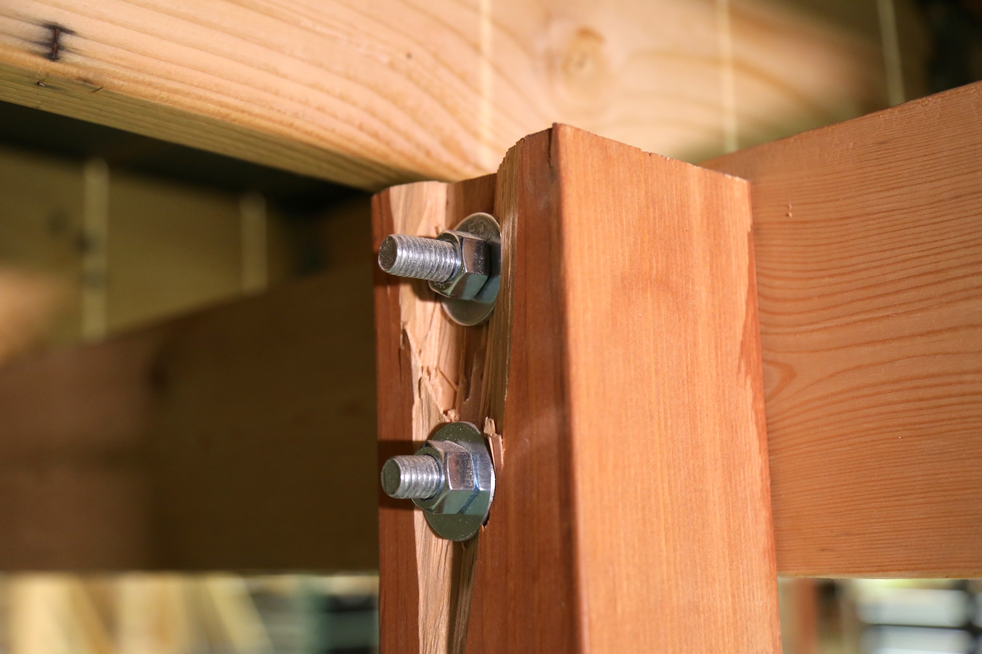
One post is damaged where the through-bolts penetrate. 

OBSERVATION #8
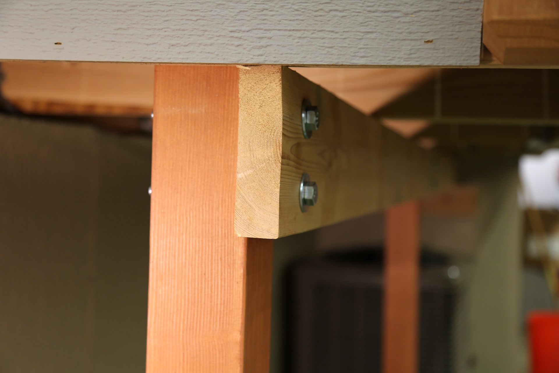
The main deck beam is undersized. It's made of only a single board.

The deck beam size depends upon the wood species and the deck joist span. The minimum size of a deck beam should be made of two 2x6 boards, and the deck beam depth should be greater than or equal to the depth of the joists.

Deck beams are permitted to cantilever at each end up to 1/4 of the actual beam span.

OBSERVATION #9
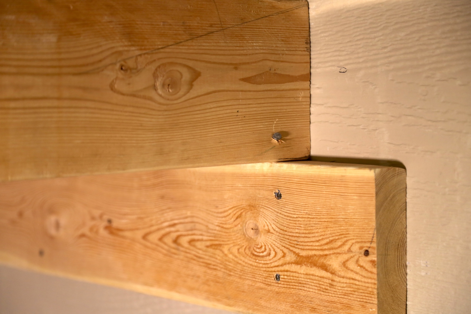
The deck beam is inadequately supported at the house wall. 

OBSERVATION #10
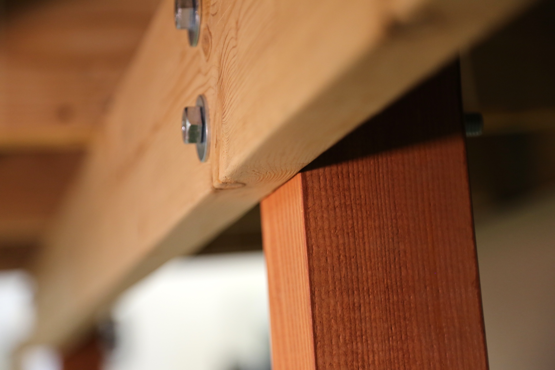
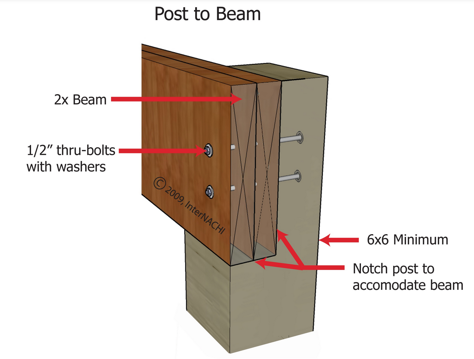
The deck beam has no direct bearing on the posts. A beam should not rely on the shear strength of lag bolts or screws. A deck beam should bear directly on the deck post that uses:

  • a notched post;
  • an approved post cap connector; or
  • other equivalent means that resists lateral displacement.

All bolts should have washers under the head and nut.
OBSERVATION #11
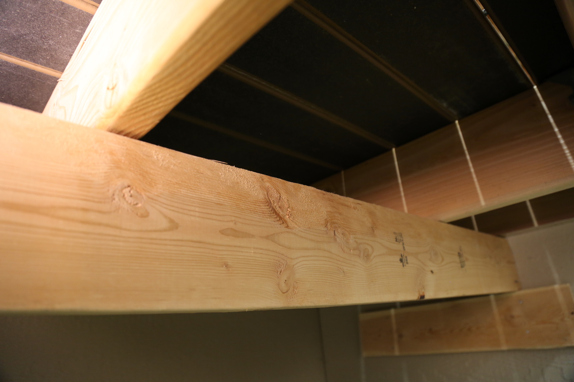
Solid blocking between the joists and above the deck beam is recommended. 

OBSERVATION #12

Not all of the joists are nailed to the deck beam. There should be a connector at each joist and beam connection point to create a continuous load path. Joists that bear on a beam must be connected to the beam to resist lateral displacement.

A continuous load path is a method of construction that uses metal connectors to create a series of solid connections within the structure of the deck. This path transfers the load or weight of the deck through its frame and into the ground and adjacent support structure (typically the house). If the deck is built with a continuous load path, it will be better equipped to resist the forces that can weaken the deck.

OBSERVATION #13

Ledger Attachment

The most common cause of deck collapse is when a ledger pulls away from the band joists of homes and buildings.

The two most common ways to correctly attach a ledger to a structure are with lag screws or through-bolts. Where supported by attachment to an exterior wall, decks should be positively anchored to the house. And that anchored attachment can not be accomplished by the use of toenails or nails subject to withdrawal.

The bolts at the ledger board are inadequately sized.

For decks connected to the band joist of the house, the deck ledger should be connected to the house with lag screws or bolts that are at least 1/2-inch diameter in size. The tip of the lag screw must fully extend beyond the inside of the band joist.
 
Ledger Board
 
Deck ledger boards must be a minimum 2-inch by 8-inch pressure-preservative-treated southern pine, incised pressure-preservative-treated Hem-fir, or approved, naturally durable, No. 2 grade or better lumber.


OBSERVATION #14

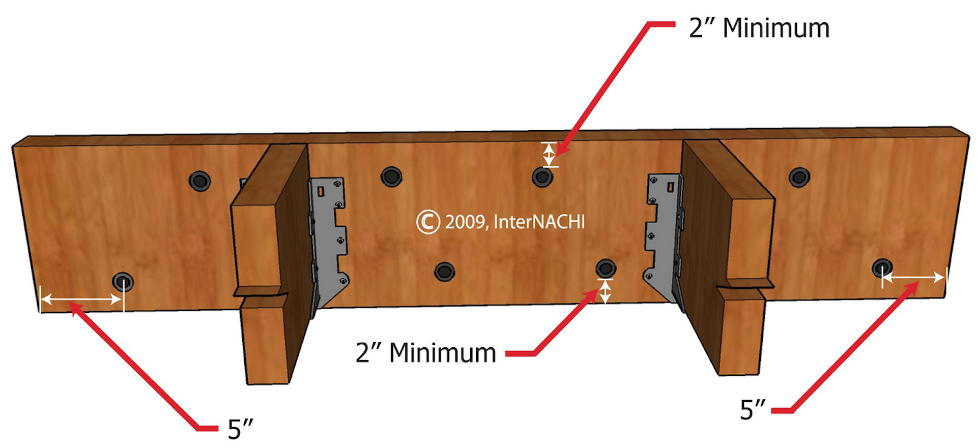
The ledger bolts are not properly spaced. 

Determining the exact required spacing for the ledger fasteners is based on many factors, including:
  • joist length;
  • type of fastener;
  • diameter of fastener;
  • sheathing thickness;
  • use of stacked washers;
  • type of wood species;
  • moisture content;
  • band joist integrity; and
  • deck loads...

...and so is beyond the scope of a home inspection. However, the spacing of ledger fasteners required is primarily determined by the length of the joists. 

InterNACHI's ledger fastener spacing formula provides inspectors with this rule of thumb:

On-center spacing of ledger fasteners in inches = 100 ÷ joist length in feet.
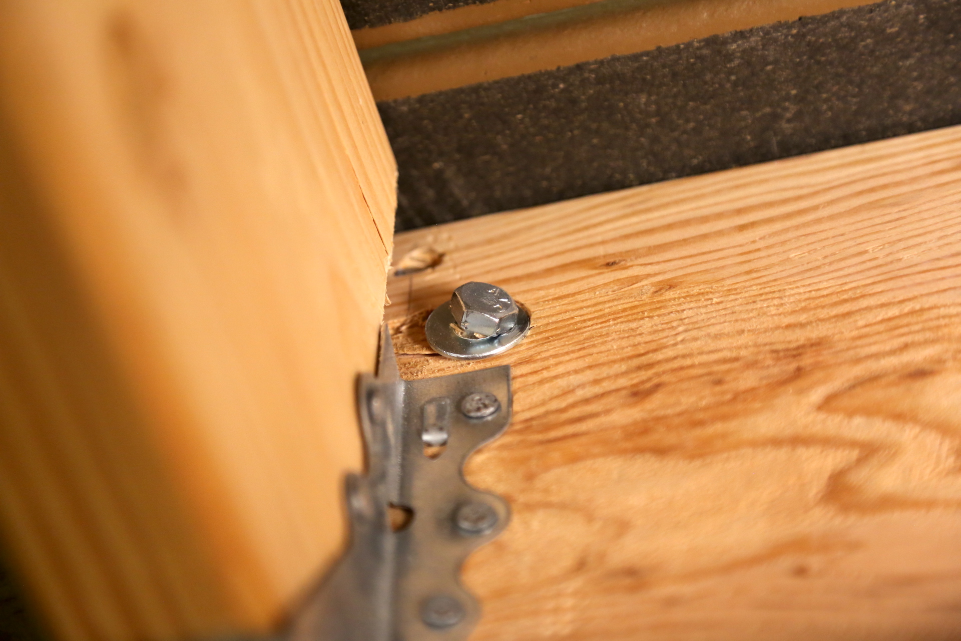
A deck with substantially fewer ledger fasteners than that recommended by InterNACHI's formula may be unsafe.

The ledger bolt is not installed perpendicular to the ledger board. It's installed at an angle. 

OBSERVATION #15
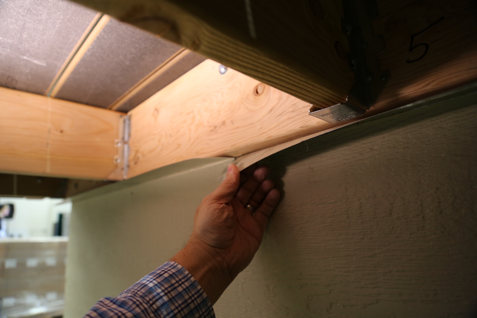
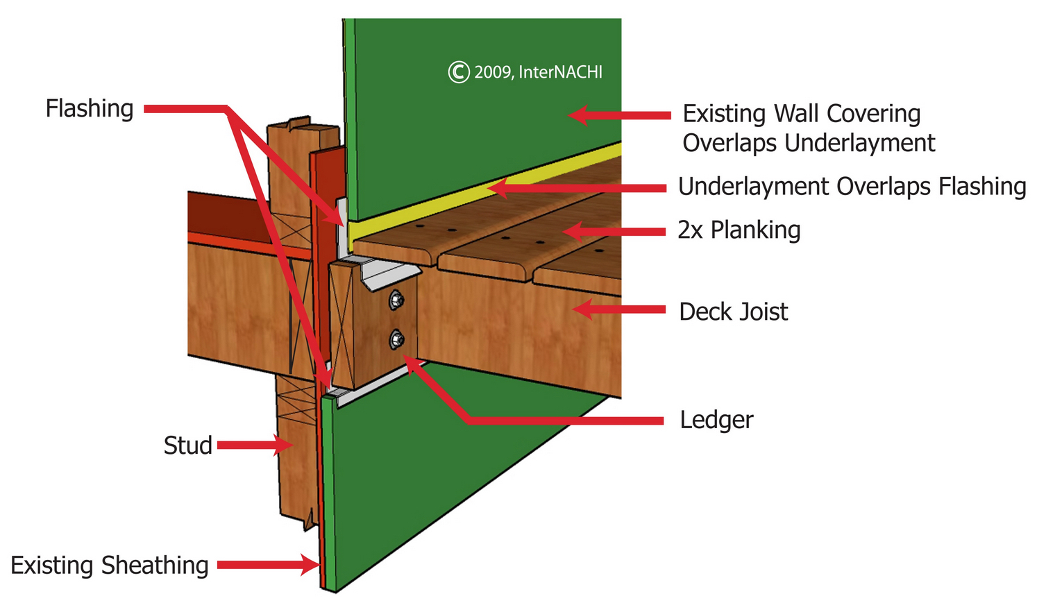
The flashing material at the top and bottom of the ledger board is improperly installed. The ledger board flashing should z-type flashing and not a simple angle flashing.
OBSERVATION #16

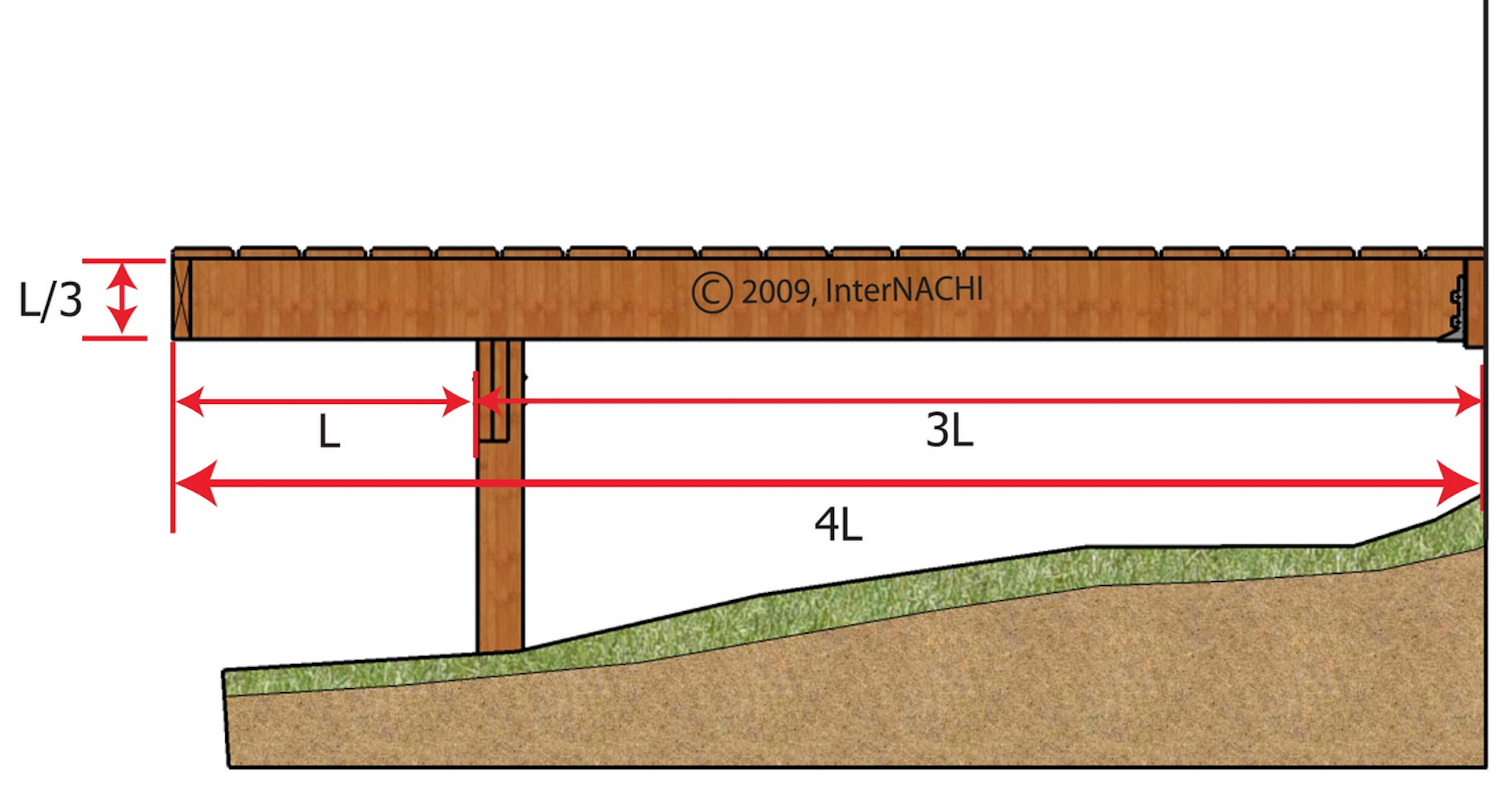
The deck floor structure is cantilevered past the deck beam. Joists should be cantilevered no more than one-quarter of the joist length and three times the joist width (nominal depth). Both conditions must be true.
OBSERVATION #17

There are open gaps of space between the bottom of joists and the joist hanger pocket. 

OBSERVATION #18
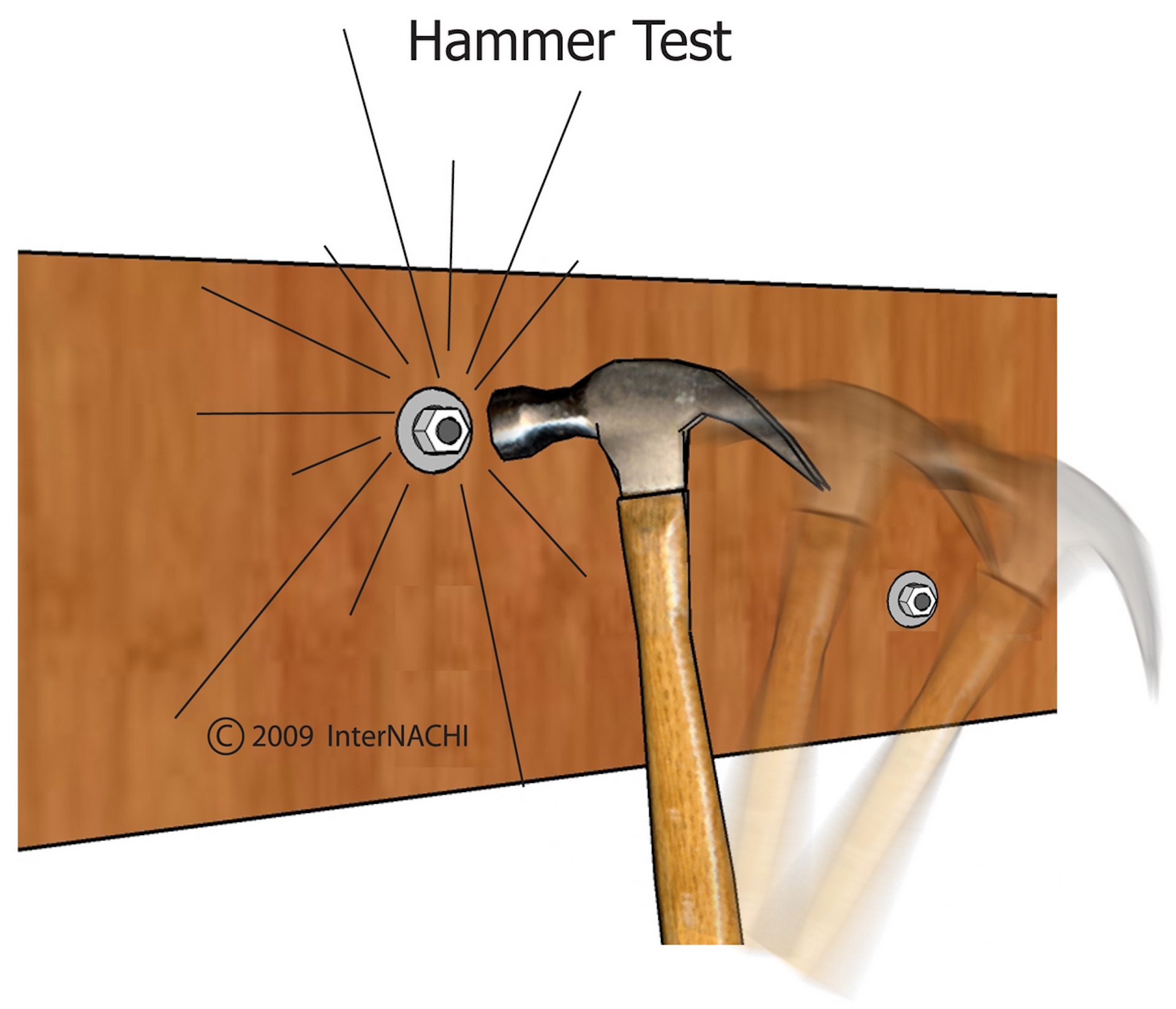
If it is not possible to reach both sides of a bolt, it may be struck with a hammer. The ring will sound hollow with vibration if the fastener is loose. The ring will sound solid if the connection is tight. The hammer test is subjective, so the inspector should hammer-test bolts that can be confirmed as tight or loose, and compare the sounds of the rings to develop a control.

OBSERVATION #19
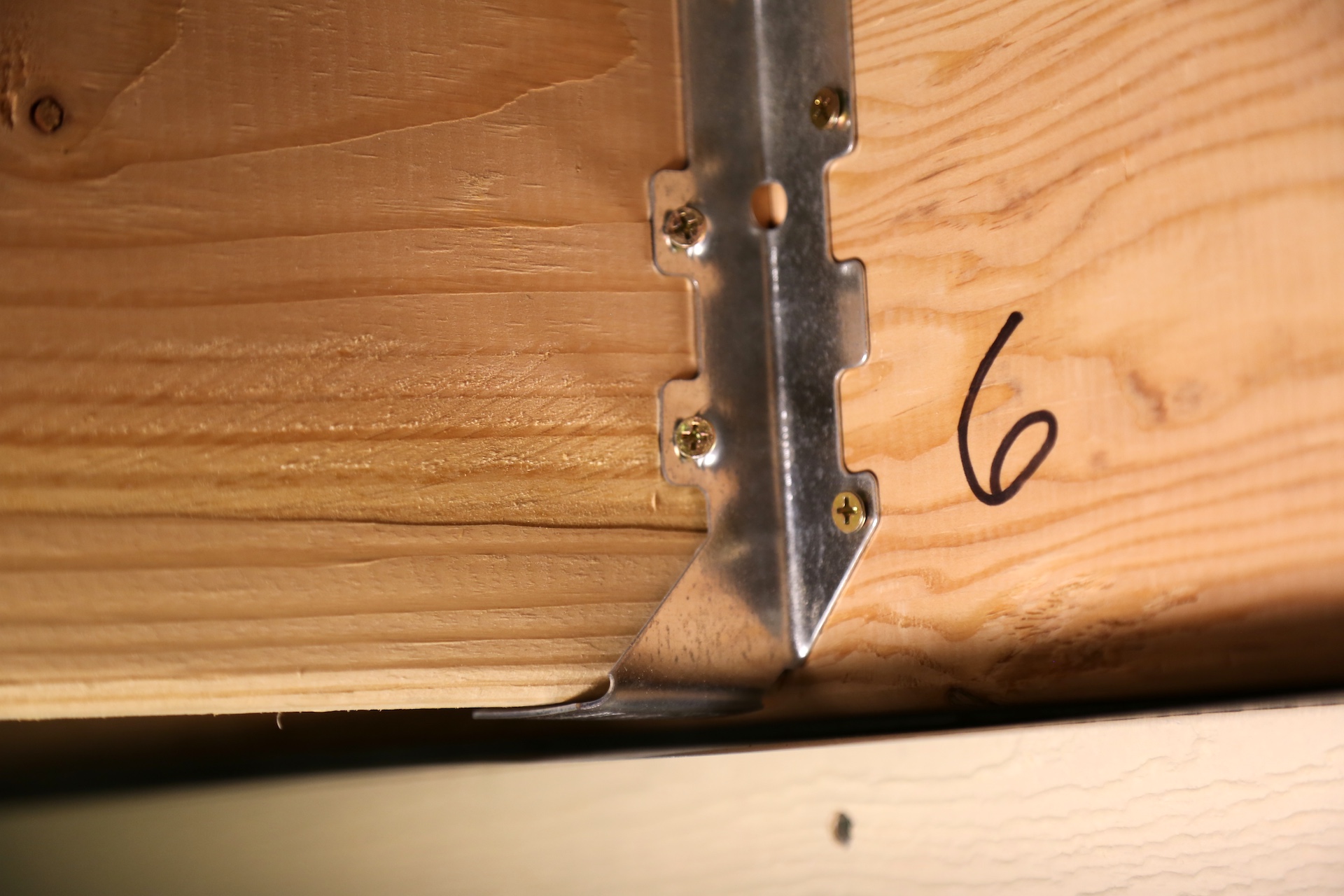
The wrong type of fasteners are installed at the joist hangers.

All screws, bolts and nails should be hot-dipped galvanized, stainless steel, silicon bronze, copper, zinc-coated or corrosion-resistant. Metal connectors and fasteners can corrode over time, especially if a product with insufficient corrosion-resistance was originally installed. Corrosion of a fastener affects both the fastener and the wood. As the fastener corrodes, it causes the wood around it to deteriorate. As the fastener becomes smaller, the void around it becomes larger. Inspectors normally do not remove fasteners to check their quality or size, but if the inspector removes a fastener, he should make sure that removal doesn't result in a safety issue. Fasteners removed should be from areas that have the greatest exposure to weather. Some inspectors carry new fasteners to replace ones they remove at the inspection.  

OBSERVATION #20

There are joist hangers installed upside down. 

Simpson Strong Tie recommends joist hangers to be installed at the ledger board and angle brackets at the outer rim joist. 

OBSERVATION #21


The deck boards span too great of a distance between the joists. This type of decking requires floor joists to be installed 16 inches on center. 

OBSERVATION #22
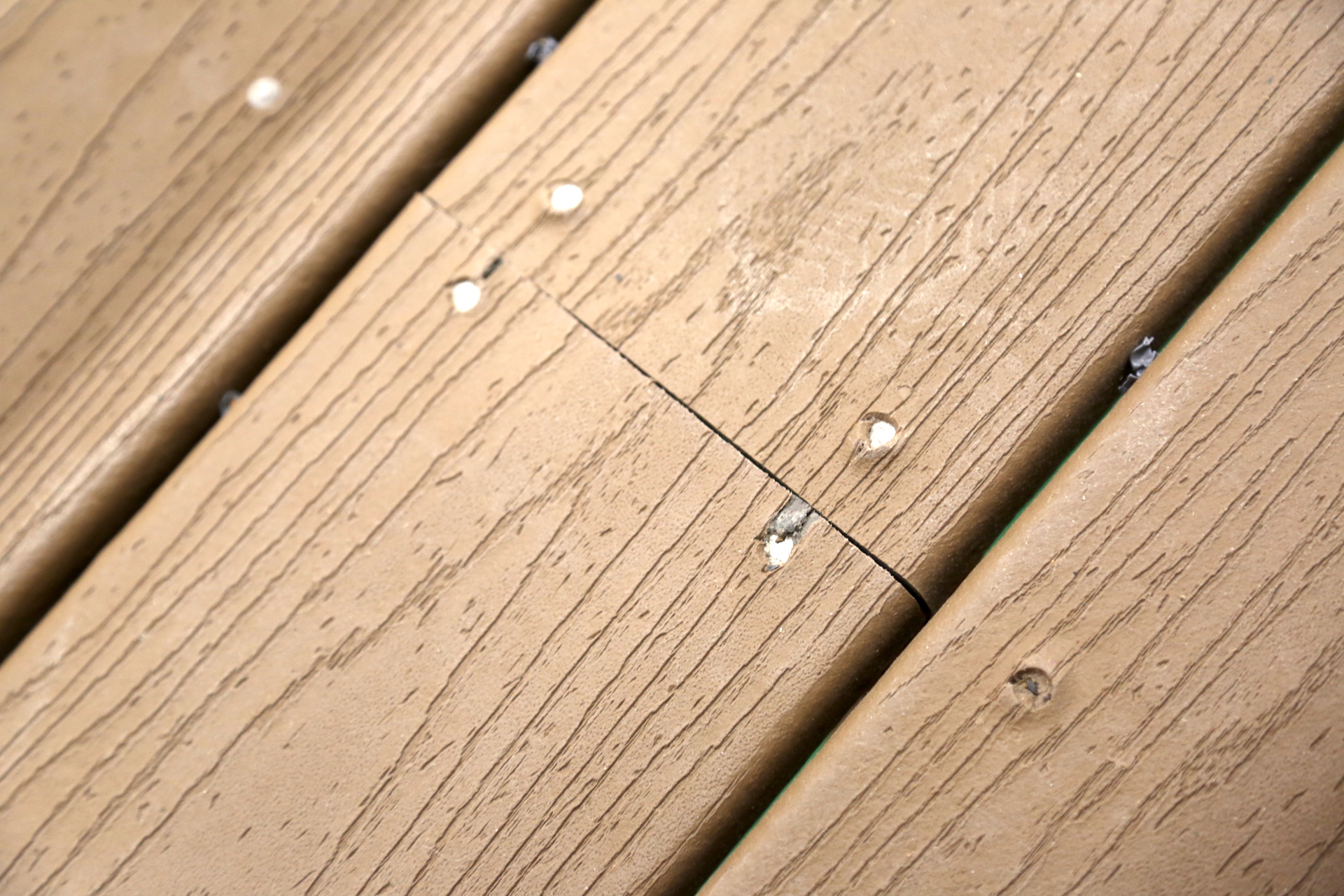
The deck floor boards should be installed with screws, not nails. 

OBSERVATION #23
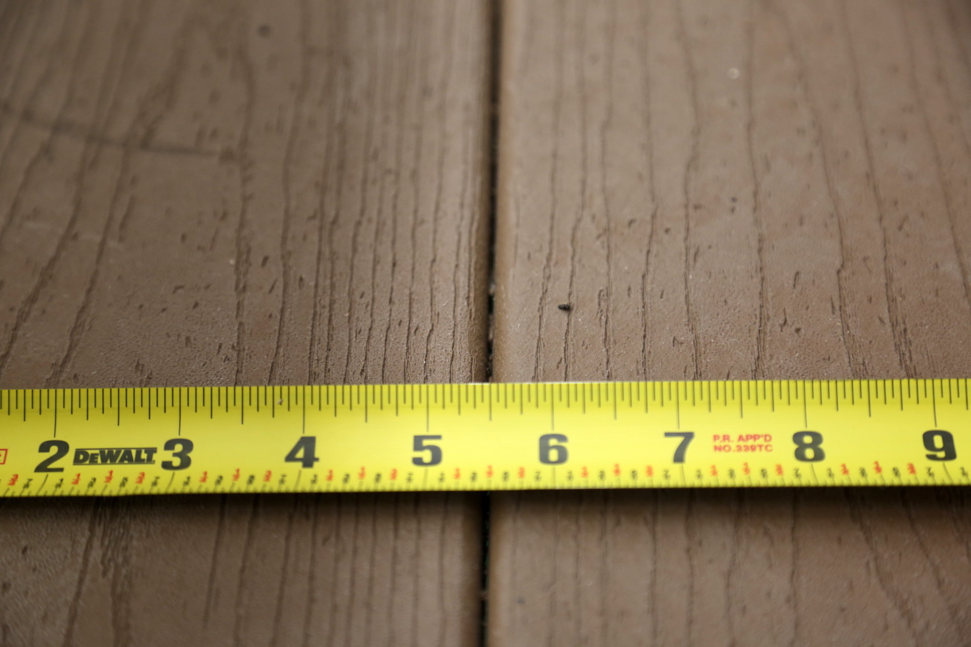
There should be a small open space between the deck floor boards to provide for expansion, contraction, and water drainage. 

OBSERVATION #24
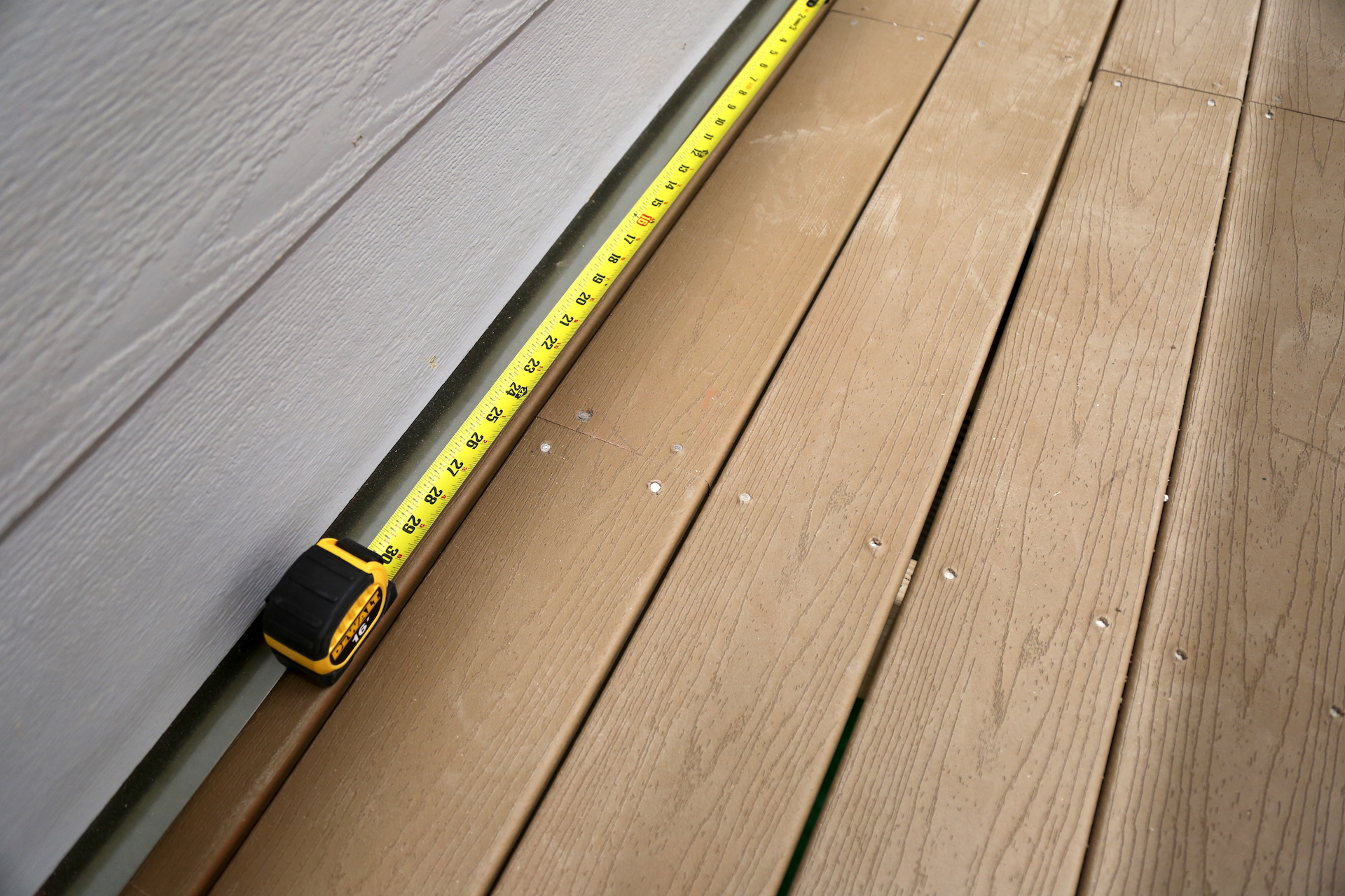
There is a deck board that spans only one joist bay. Each segment of deck boards should bear on a minimum of four joists.

OBSERVATION #25
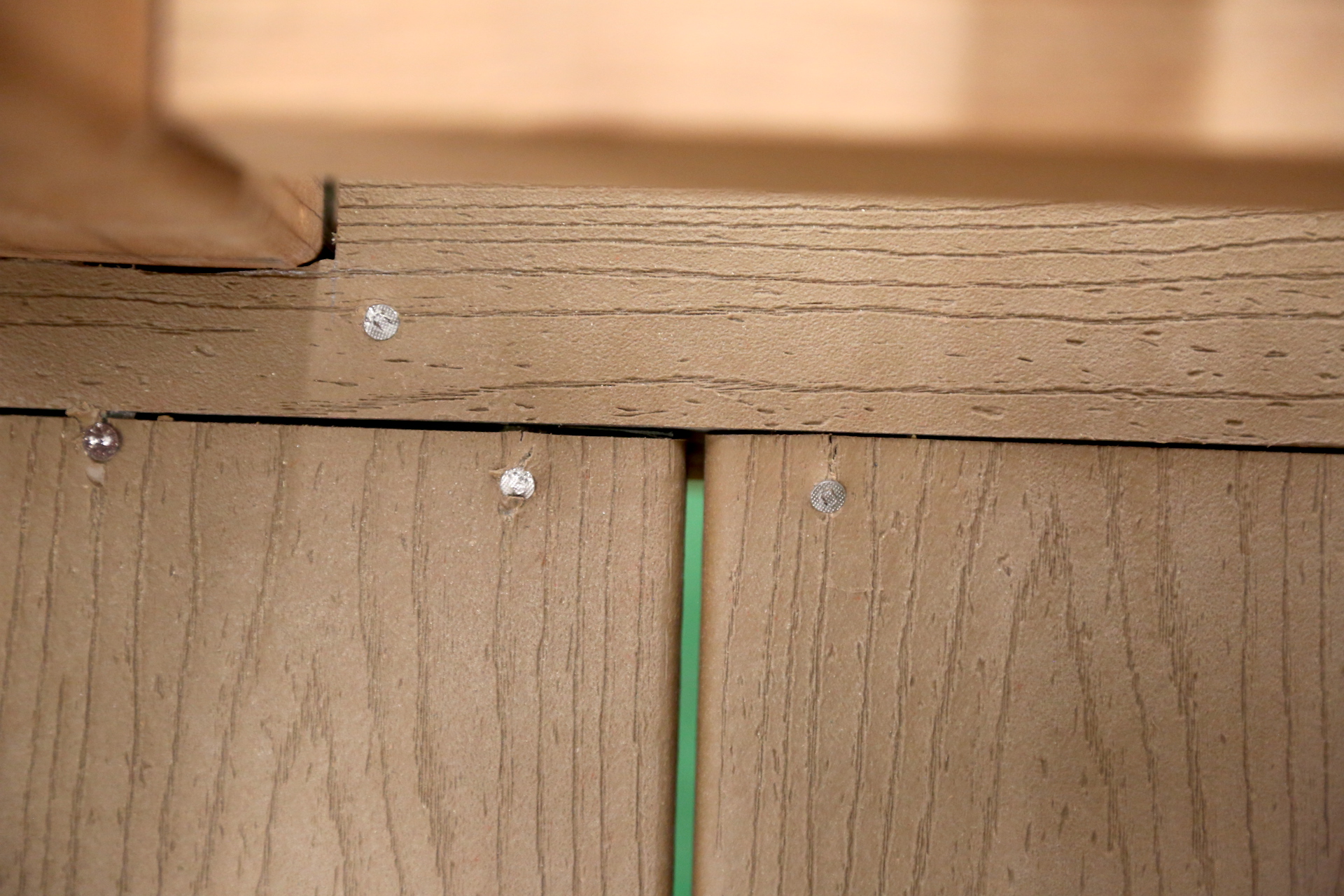
There are deck boards with inadequate bearing on their ends. 

OBSERVATION #26
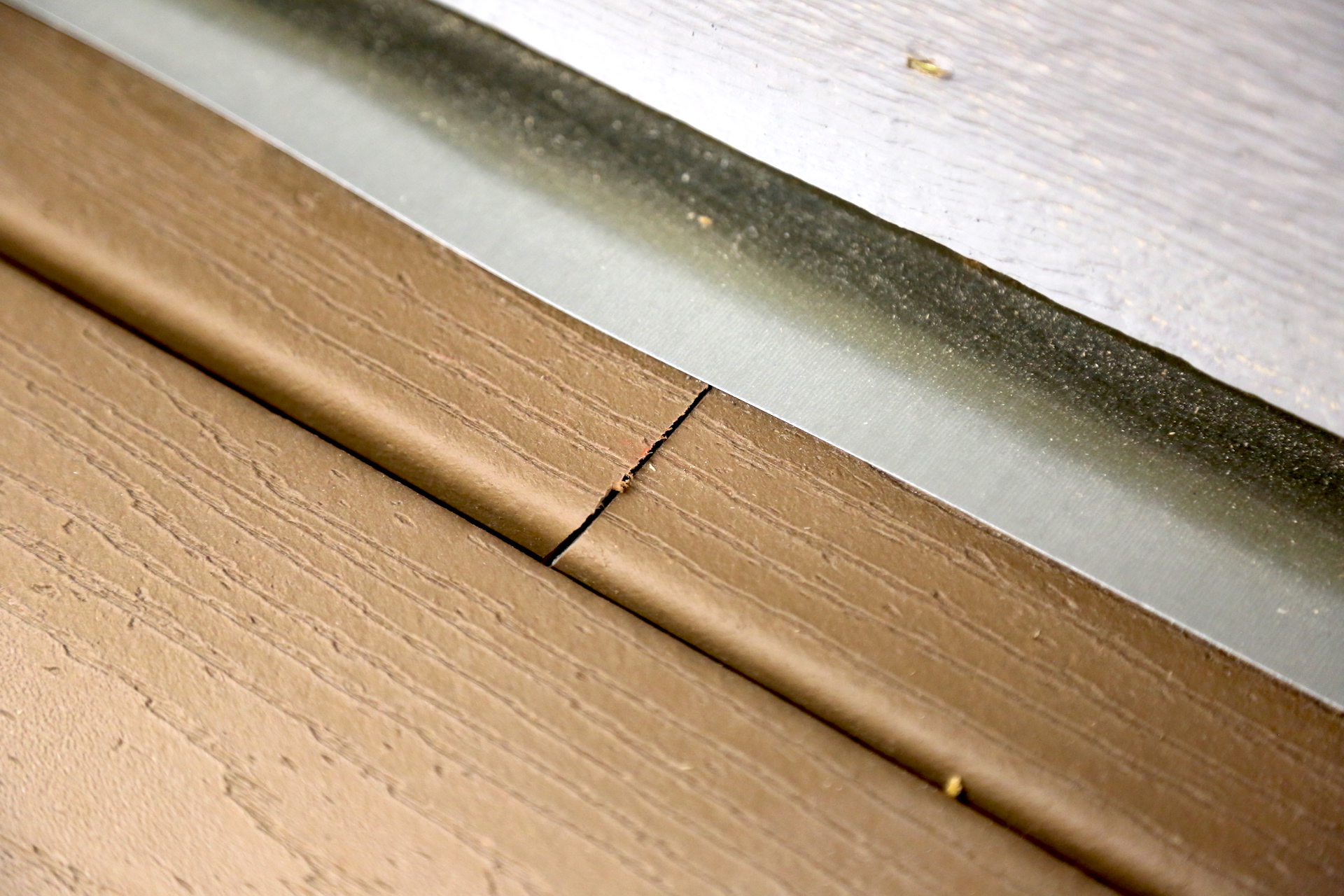
Some deck boards do not end on top of a joist. 

OBSERVATION #27
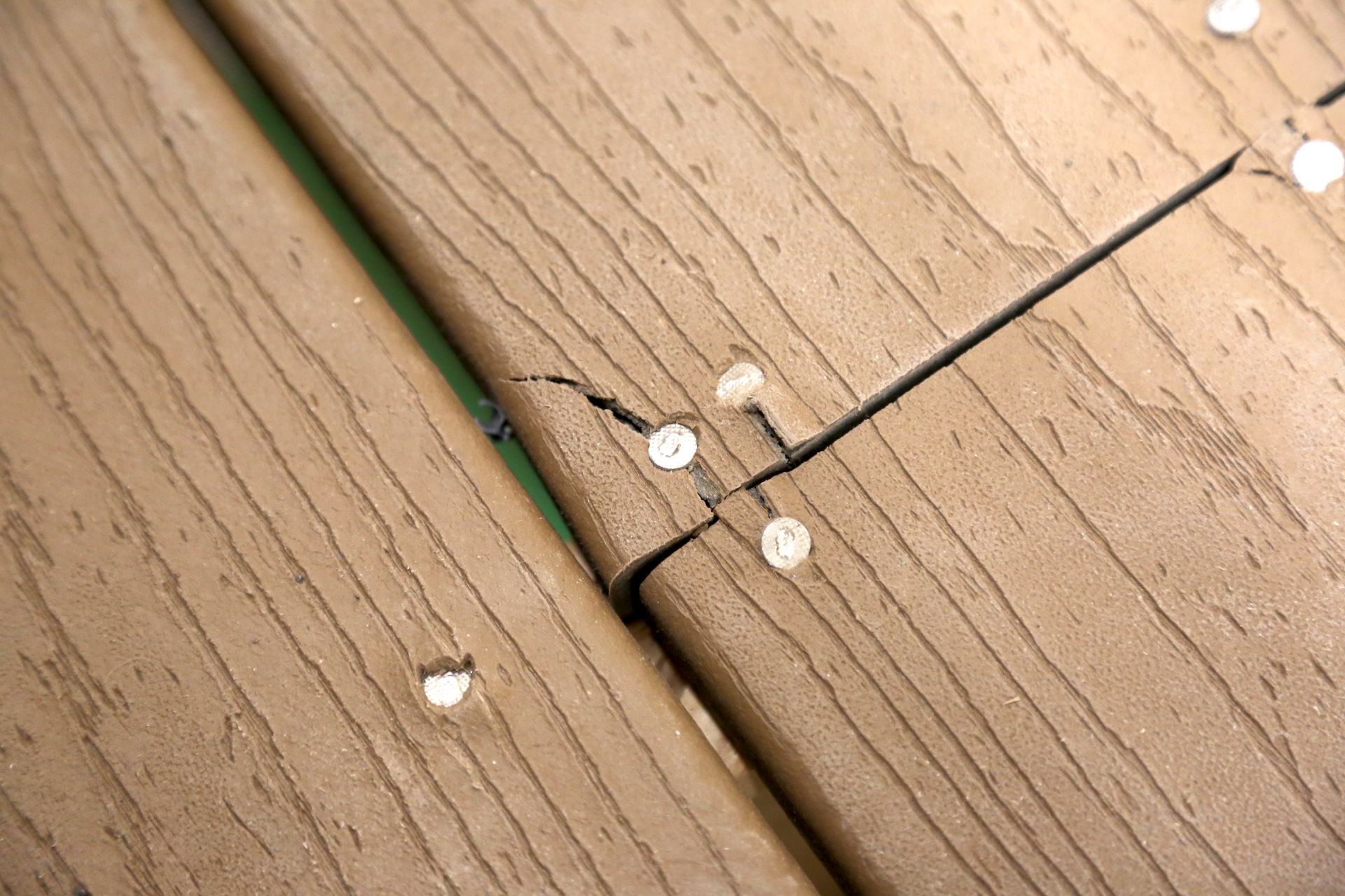
Damaged floor boards. 

OBSERVATION #28
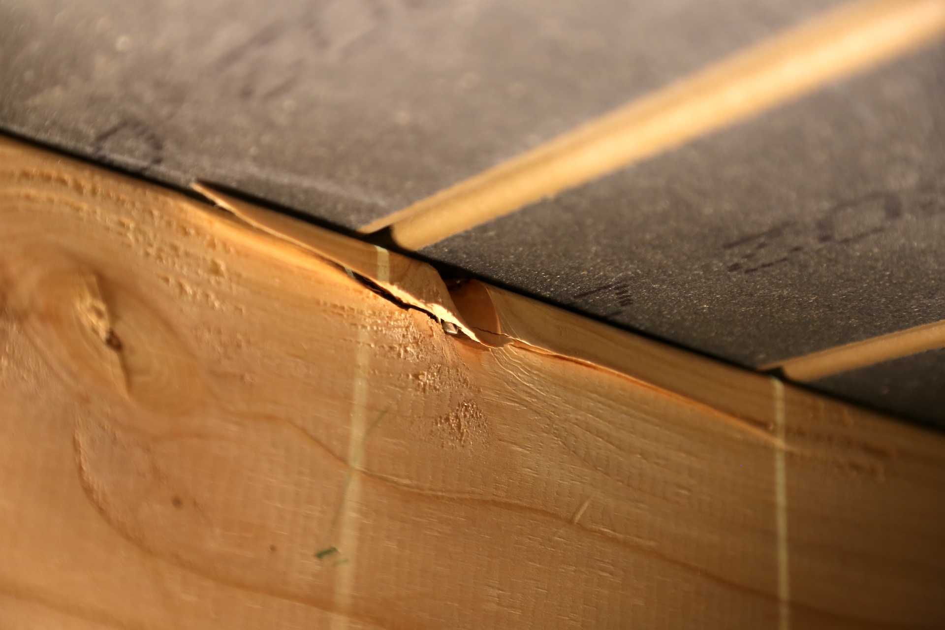
Some damage to the joist underneath the deck boards. 

OBSERVATION #29
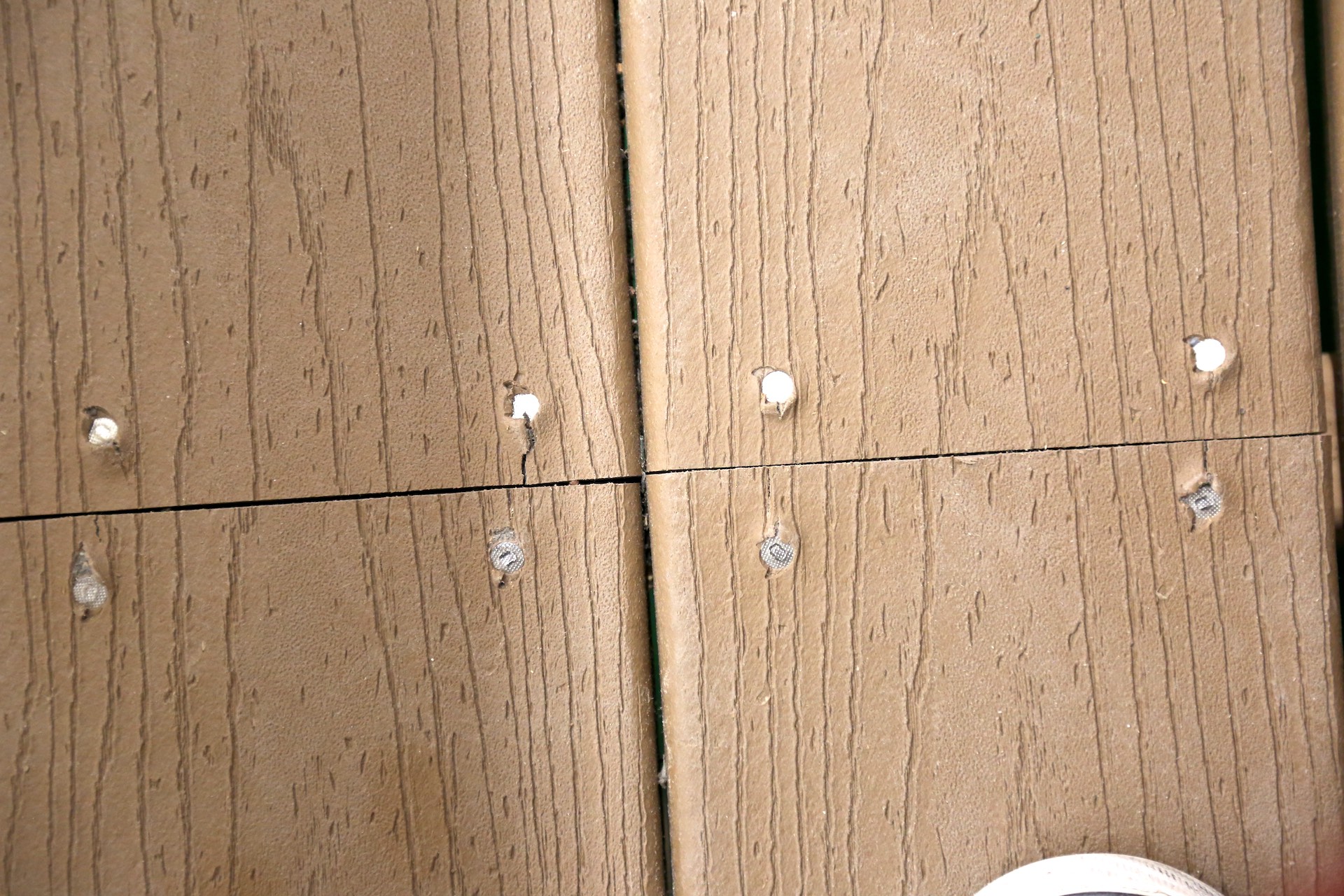
There are deck boards that are not staggered properly. Decking should be staggered so that butt joints don't land on the same joist side by side.

OBSERVATION #30
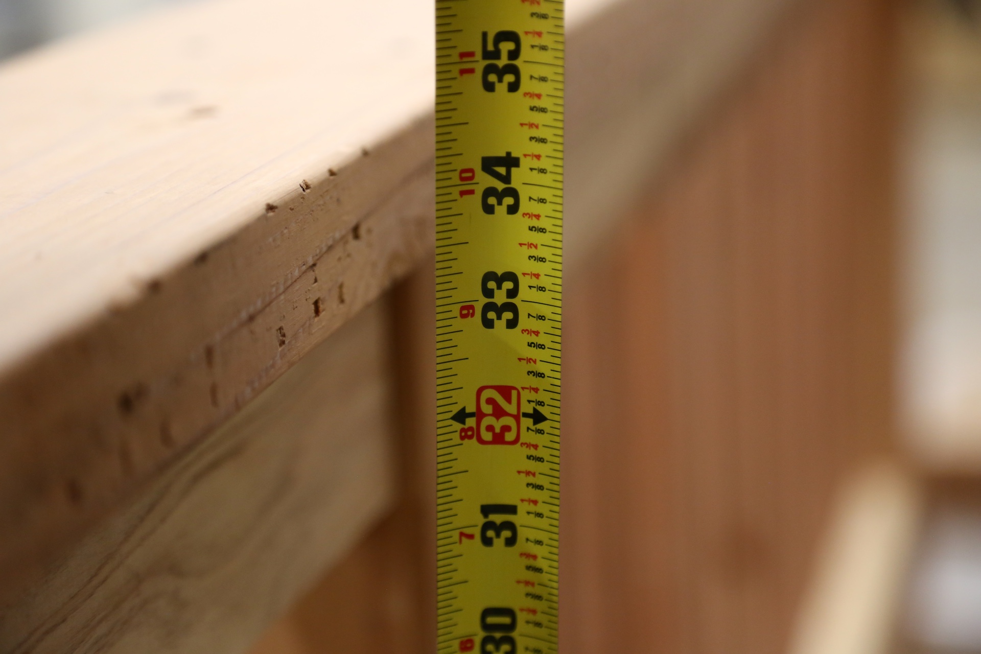
Most residential codes require the top of the guardrail to be at least 36 inches from the deck surface. Most commercial code height is 42 inches.

OBSERVATION #31
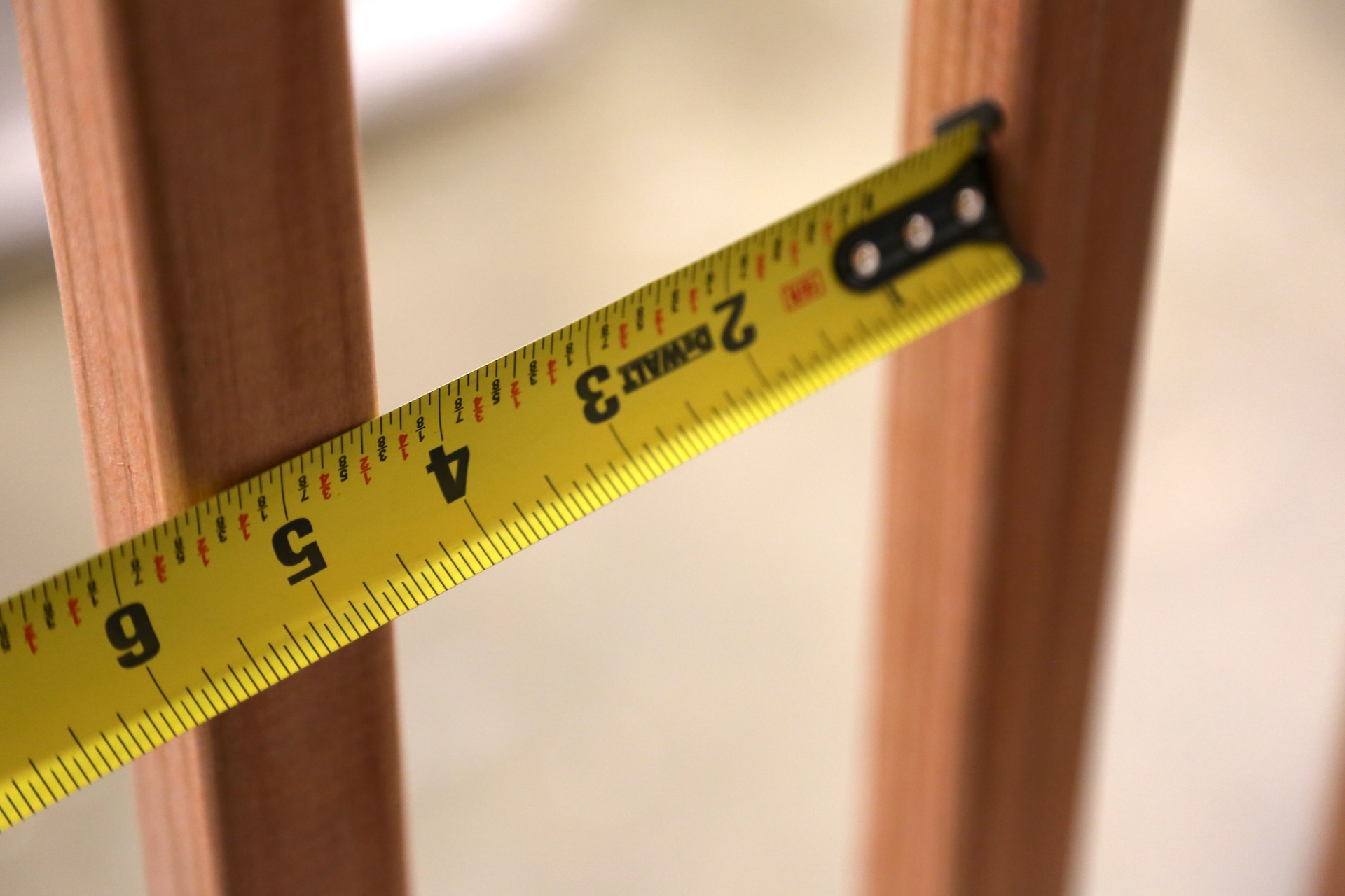
There is excessive open space between the guard in-fill components. 

The guard in-fill components should not permit a 4-inch sphere to pass through them.

OBSERVATION #32

The guard in-fill components (or balusters) should be located on the interior side of the horizontal rails. As the deck ages, the fasteners will lose significant resistance to withdrawal. 

OBSERVATION #33
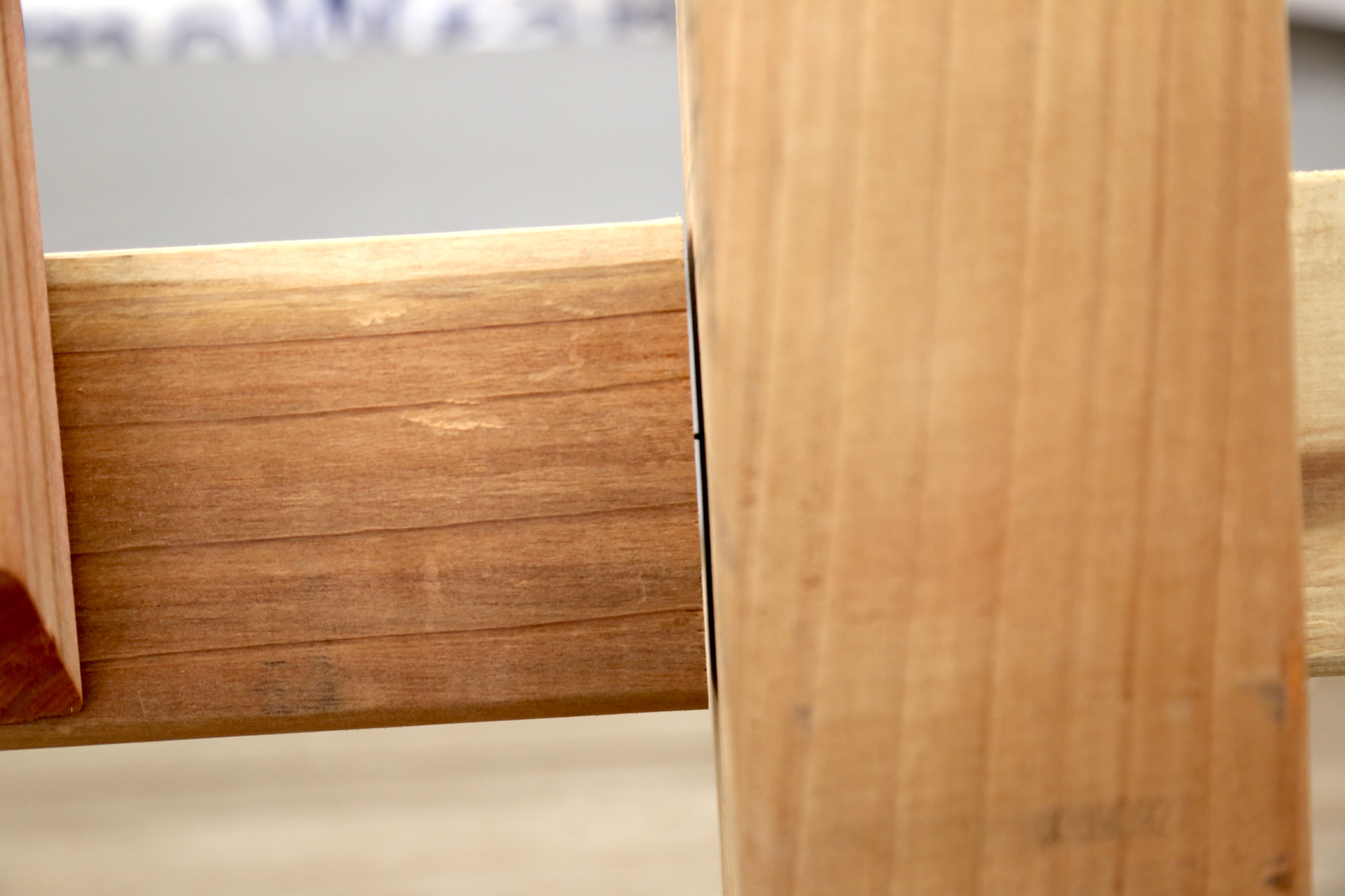
The guard in-fill components are attached to the posts with finish nails. 

OBSERVATION #34

Drywall screws are used for fastening the guard components. 

OBSERVATION #35
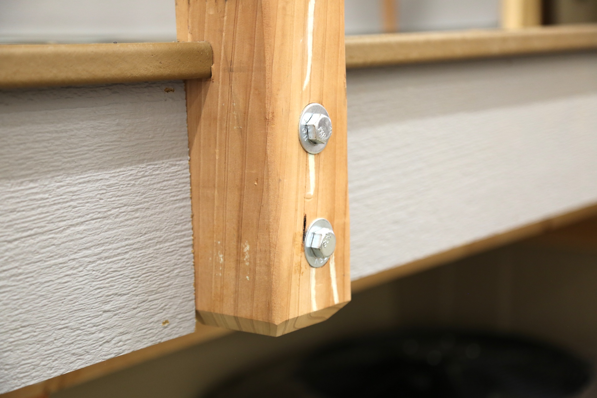
The guardrail posts are attached to the deck rim joist only. There are more reliable methods to attached the post, including metal connections. 

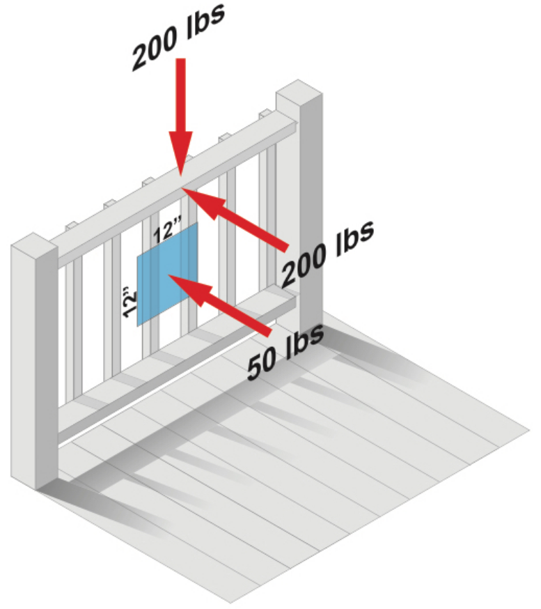
This common notched-type of attachment to the rim joist is permitted by many codes, but could become unsafe, especially as the deck ages. Because of leverage, a 200-pound force pushing the deck's guardrail outward causes a 1,700-pound force at the upper bolt attaching the post. It is difficult to attach deck guardrail posts in a manner that is strong enough without using deck guardrail post brackets.

Guard in-fill components, balusters and panel fillers must be able to withstand a horizontally applied load of 50 pounds on an area equal to one square foot. 

There is one attachment at the bottom of a guardrail post that is not tight, where the washer is loose. 
OBSERVATION #36
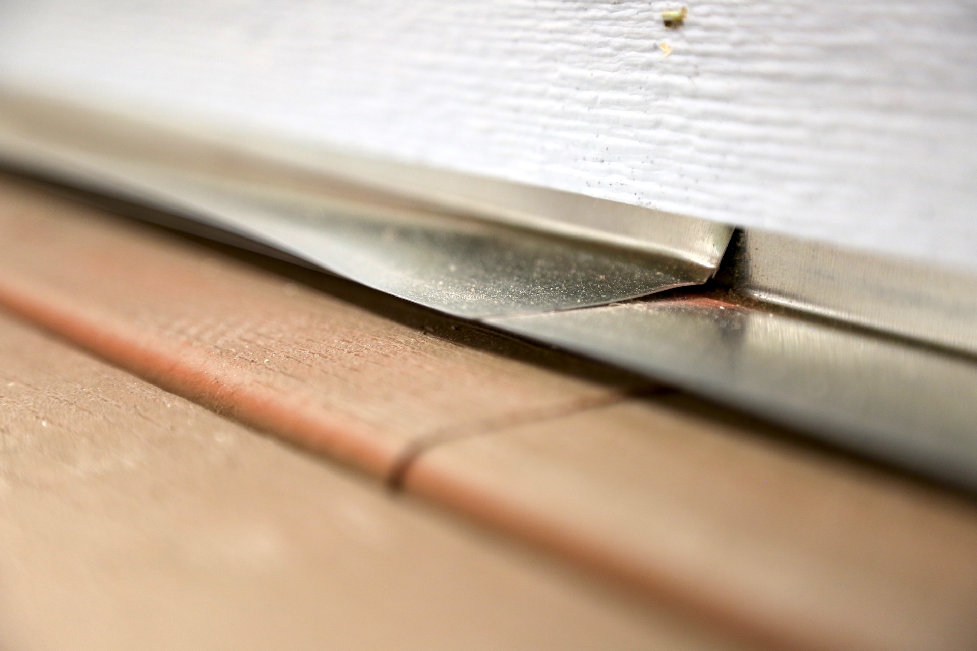
Inadequate clearance of the siding from the deck surface. 

OBSERVATION #37
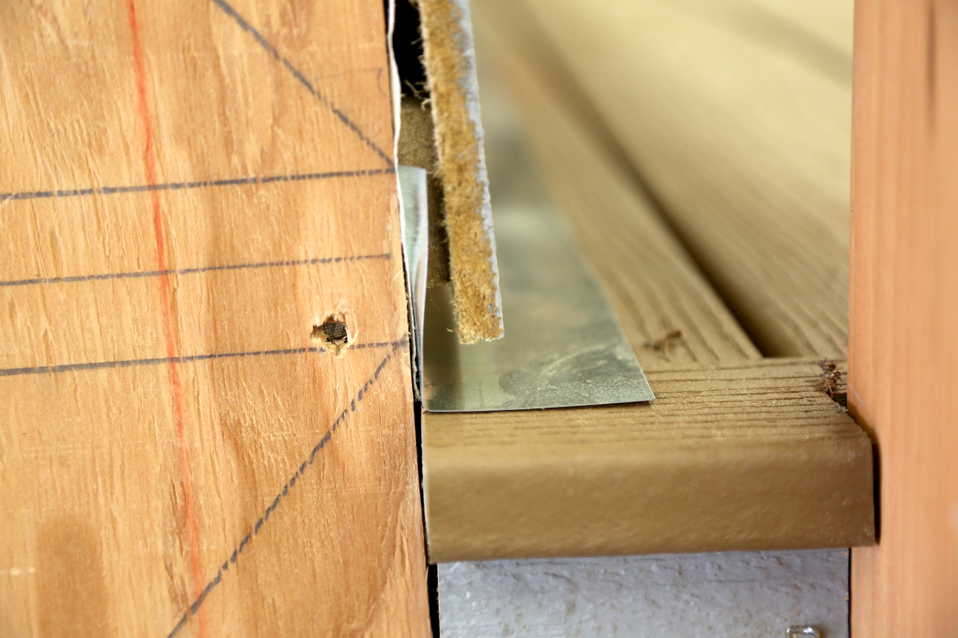
 

The Tyvek material should overlap the flashing at the ledger board area. 

OBSERVATION #38
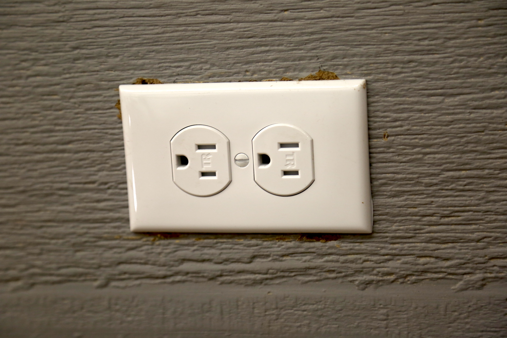
All deck receptacles should be GFCI-protected and weather-proof. 
Garage Inspection Guide

OBSERVATION #1

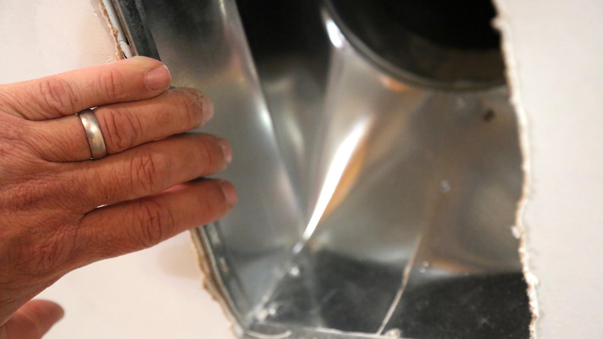
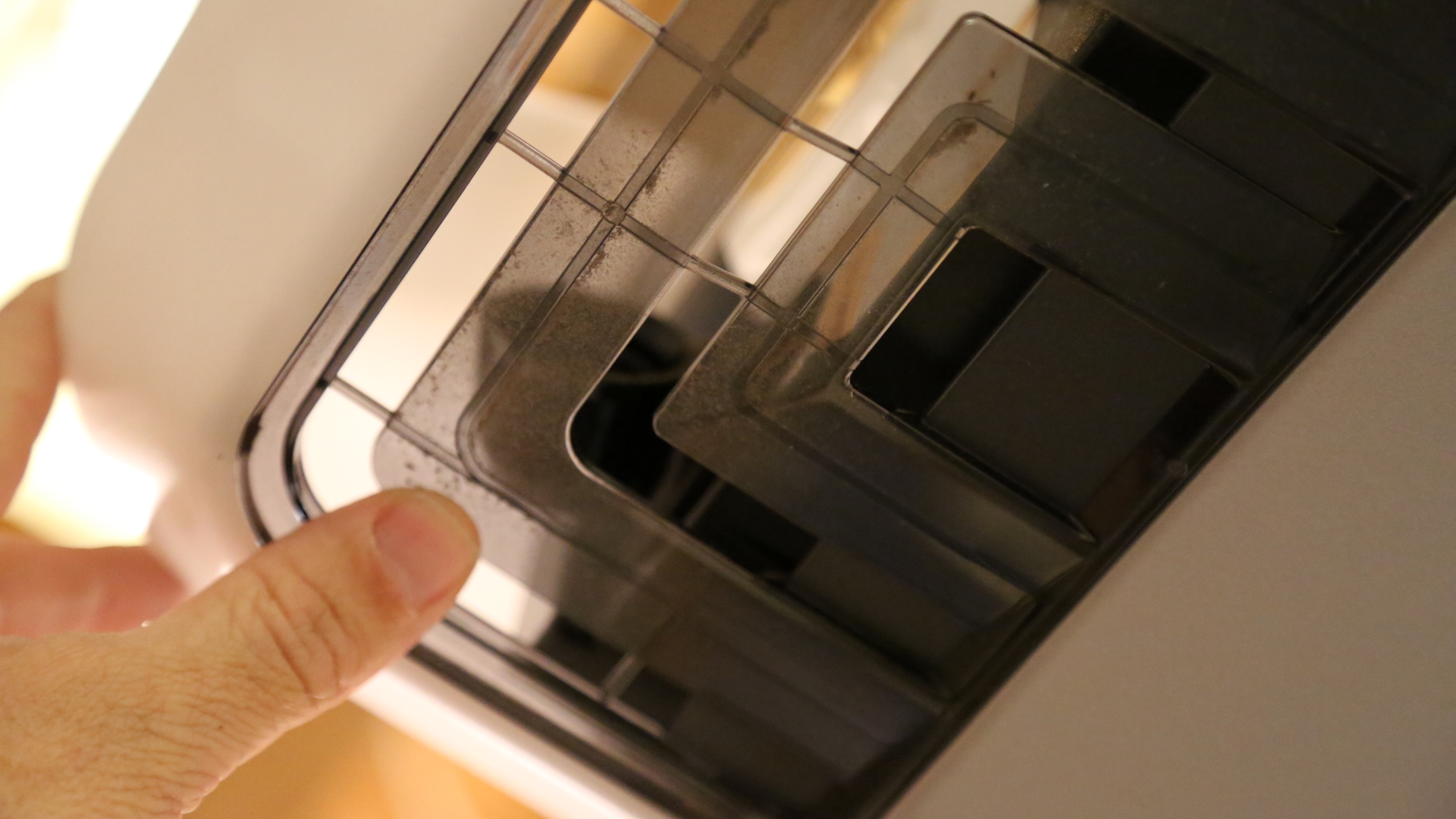
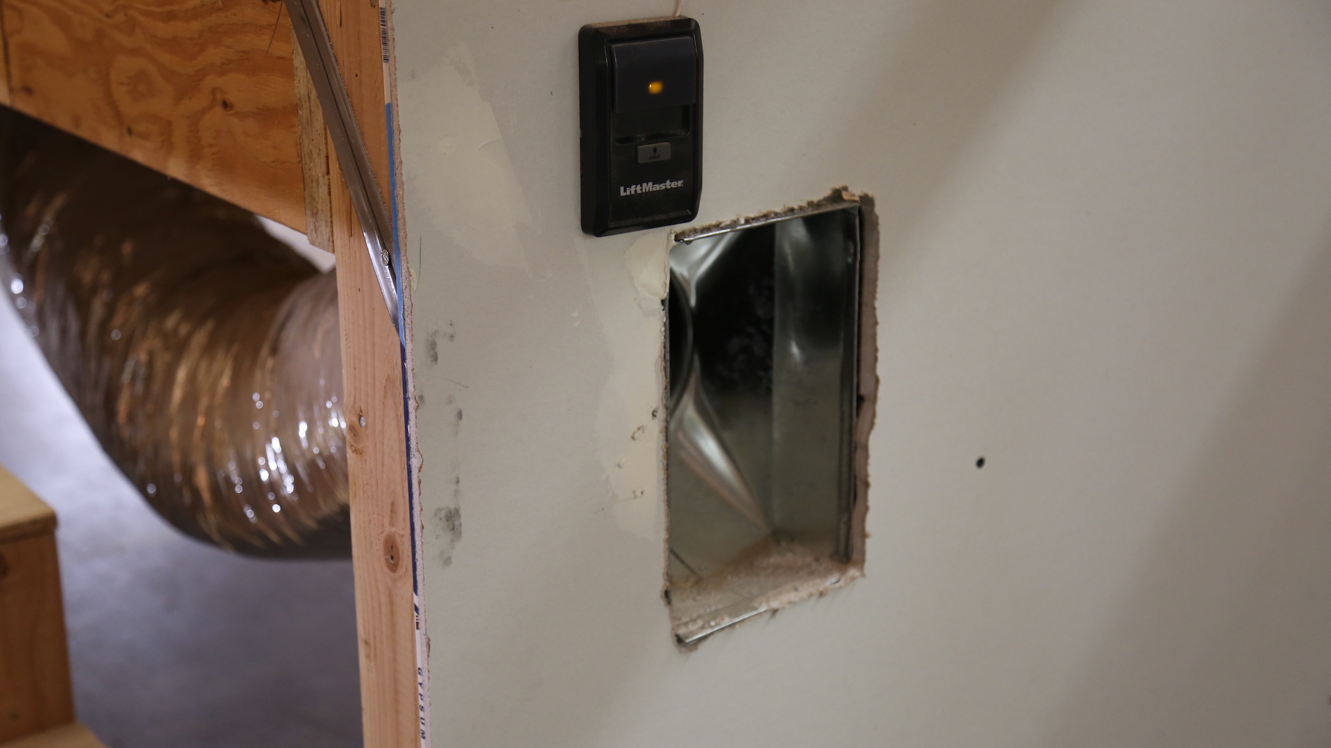
There is an open HVAC duct located on the rear wall of the garage.

According to the International Residential Code 2015 M1601.6 Independent Garage HVAC Systems, furnaces or air-handling systems that supply air to living spaces shall not supply air to or return air from a garage. Circulation of air contaminated with objectionable odors, flumes or flammable vapors is prohibited because of potential health and safety hazards.

OBSERVATION #2

There is a duct opening at the rear wall of the garage. According to IRC 2015 R302, ducts in the garage or ducts penetrating the walls or ceilings separating the house from the garage must be constructed of a minimum No. 26 gauge (0.48 mm) sheet metal or other approved material and shall not have openings into the garage.

OBSERVATION #3

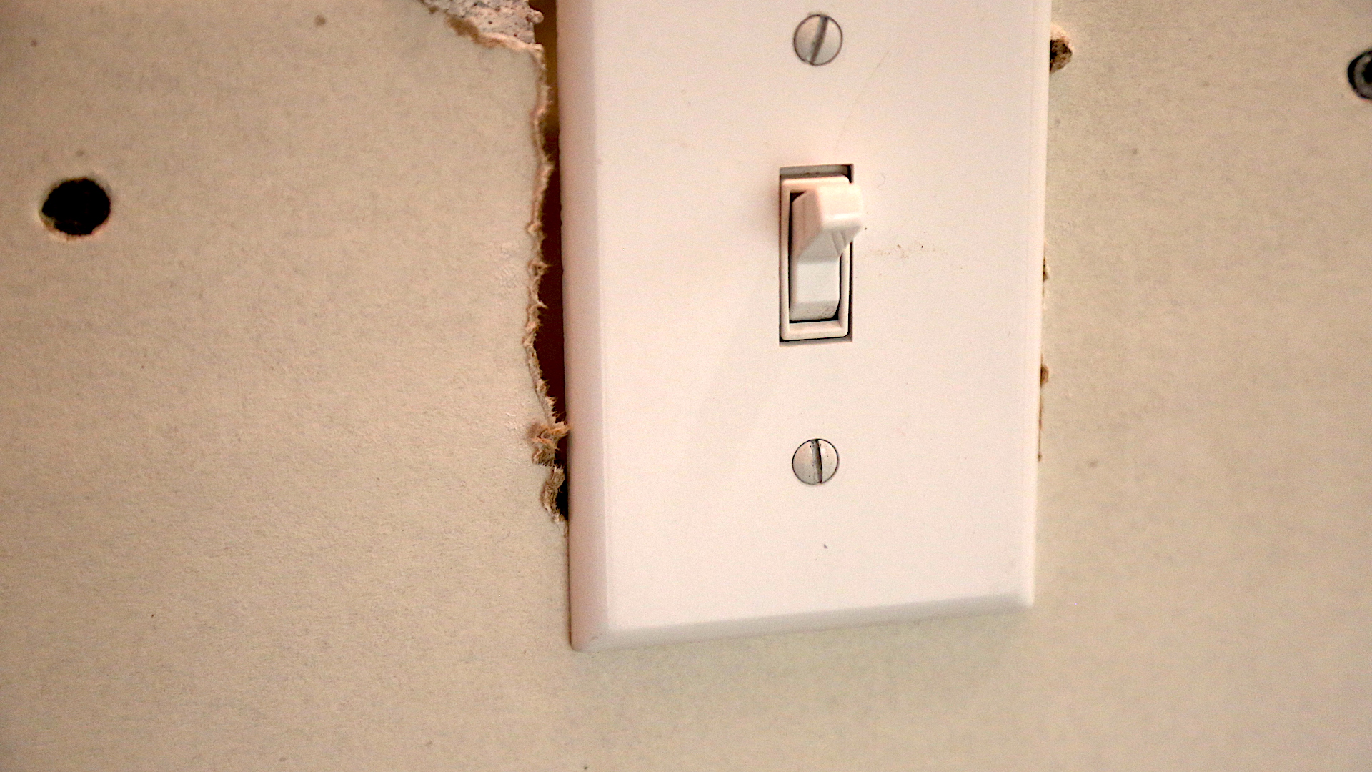
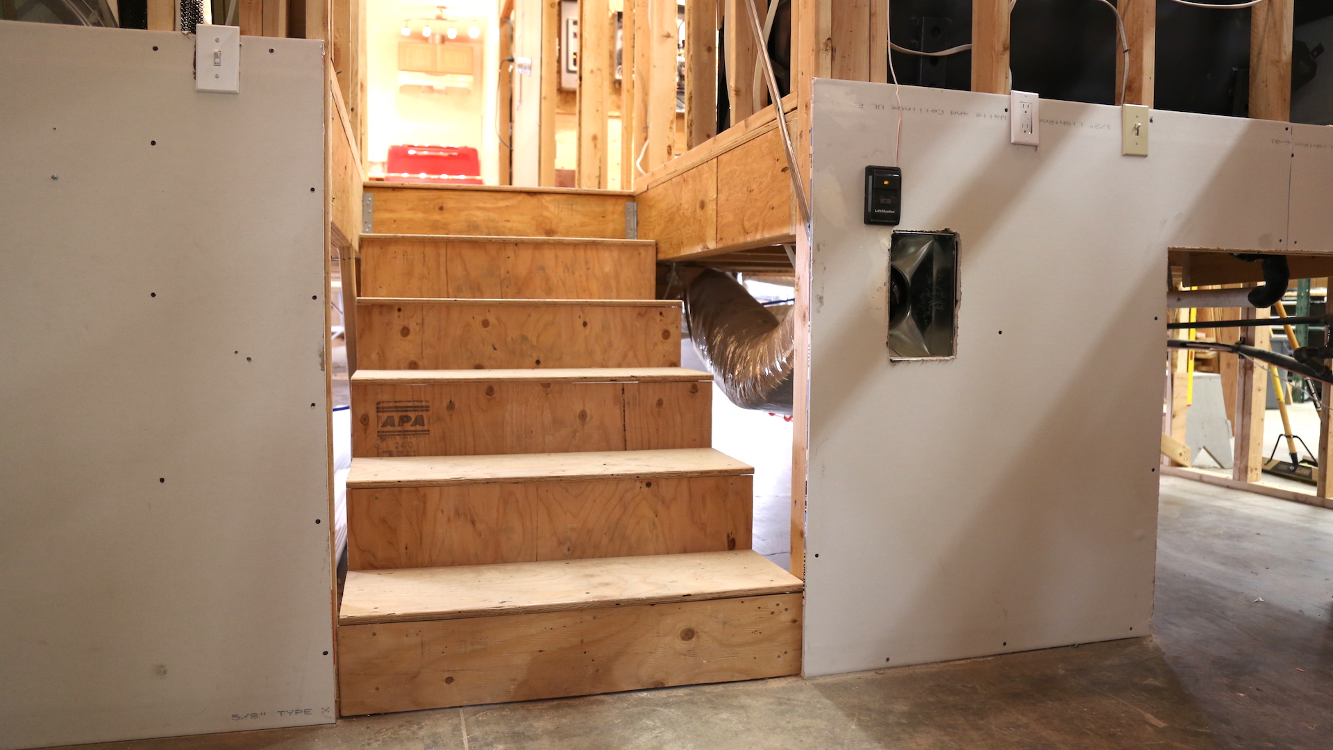
Drywall cut out for receptacles and switches violate the firewall recommendations. All openings should be sealed with joint compound or other equivalent material. 

OBSERVATION #4

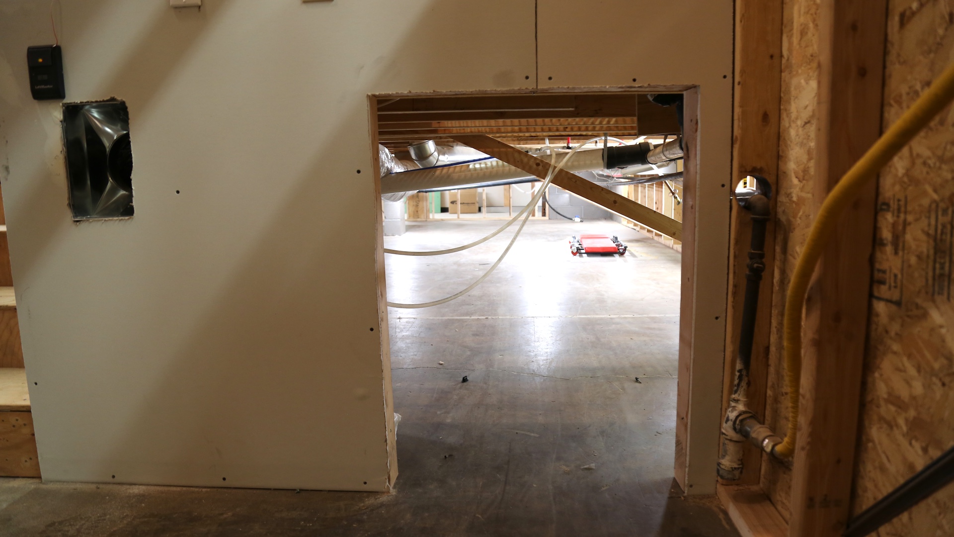
The opening from the garage to the crawlspace must be treated as a firewall. A fire-rated access door at the opening to the crawlspace is recommended.

There is also missing drywall at the garage walls and ceiling. 

OBSERVATION #5

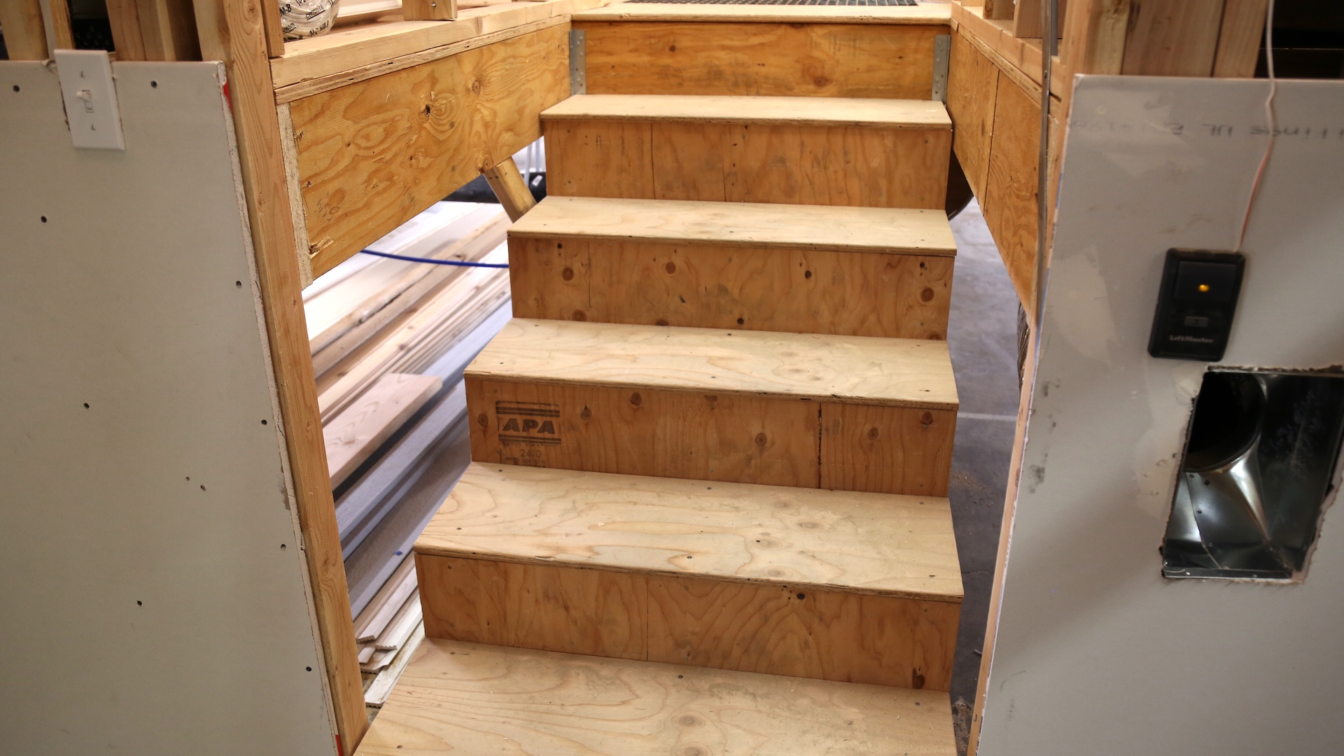
There's a direct opening between the garage and the house interior at the stairs. According to IRC 2015 R302.5.1, openings from a garage directly into a room used for sleeping purposes shall not be permitted. Other openings between the garage and house must be equipped with solid wood doors not less than 1 and 3/8 inches (35 mm) in thickness, solid or honeycomb-core steel doors not less than 1 and 3/8 inches (35 mm) thick, or 20-minute fire-rated doors, equipped with a self-closing device.

OBSERVATION #6

There is drywall (gypsum board) attached to the garage wall, but it is a defect.

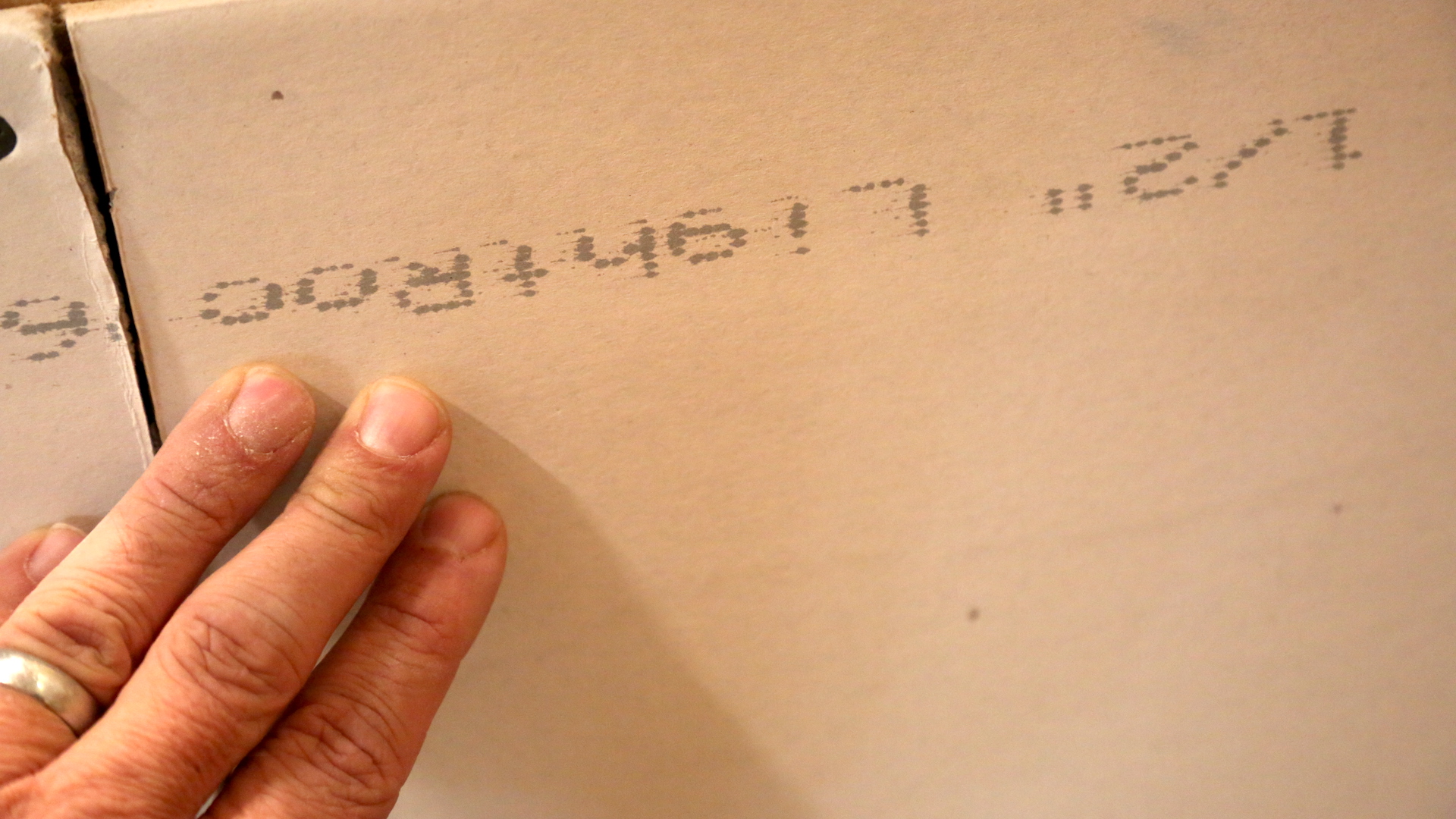
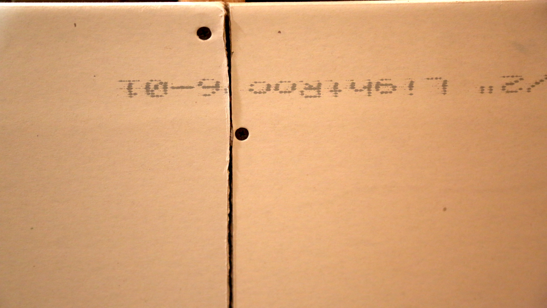
According to IRC 2015 R302, the garage shall be separated from the house. In relation to the separation from the residence and the attic, not less than 1/2-inch gypsum board or equivalent shall be applied to the garage side. From habitable rooms above the garage, there should be at least 5/8-inch Type X gypsum board or equivalent. In relation to structures supporting floor/ceiling assemblies used for separation, at least 1/2-inch gypsum board or equivalent shall be installed. For garages located less than 3 feet from a house on the same lot, at least 1/2-inch gypsum board or equivalent shall be applied to the interior side of the exterior walls that are within this area.

OBSERVATION #7

The drywall in the garage should be properly taped and coated with joint compound. According to the Gypsum Association GA-216 Application and Finishing of Gypsum Panel Products, three coats of joint compound are recommended at the fasteners, edges, ends, surfaces, openings, corners, and joints. 

OBSERVATION #8

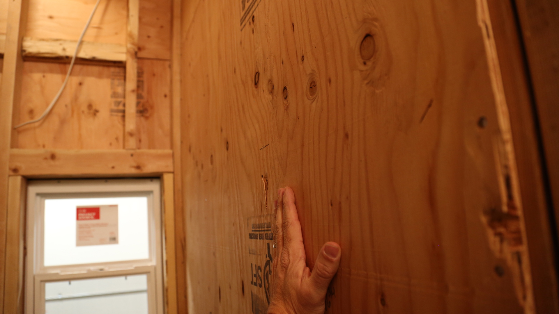
The exposed wood paneling at the back wall of the garage is a fire hazard.

OBSERVATION #9

The garage floor surface is made of a noncombustible material but the garage floor is not sloped. The floor of a garage used for parking automobiles or other vehicles must be sloped to a drain or toward the main vehicle entry doorway to facilitate the movement of grease, flammable liquids or other hazardous material.

OBSERVATION #10

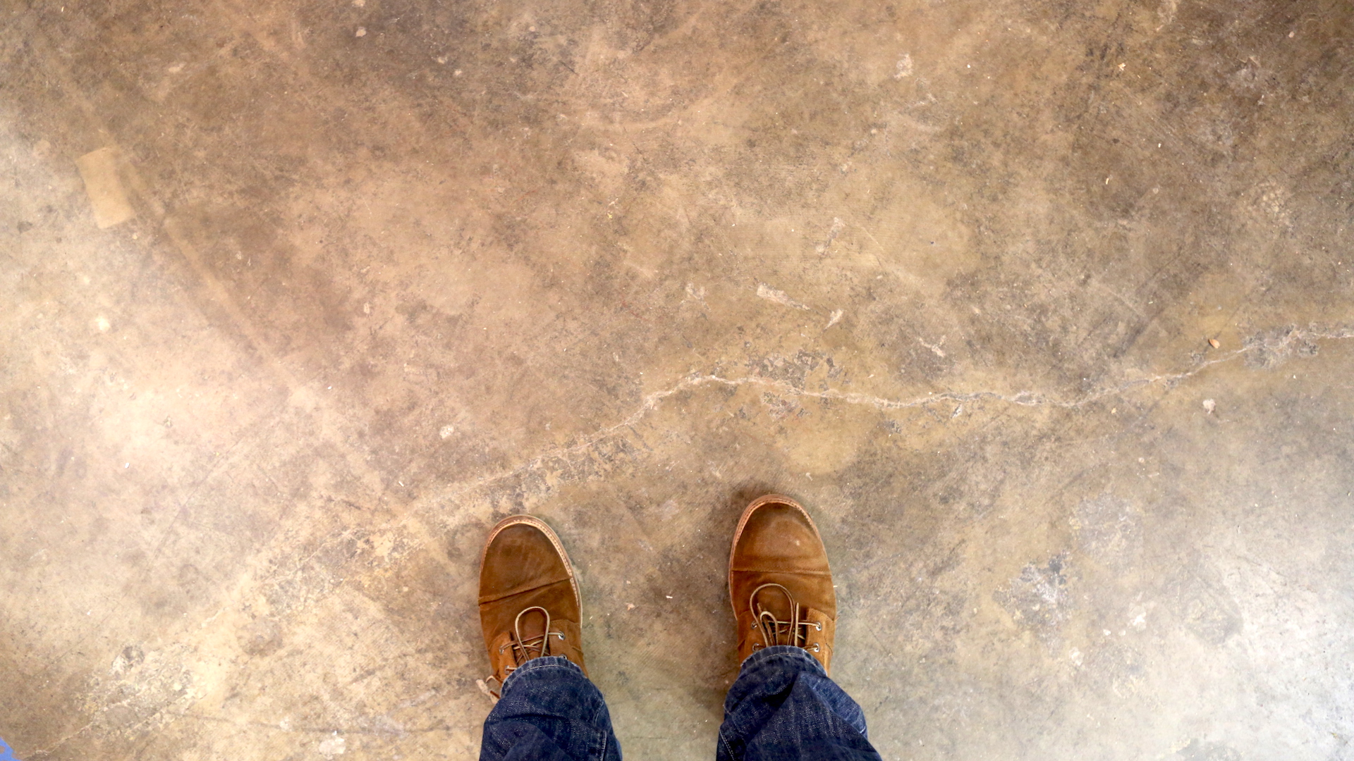
Joints are used in slab-on-ground construction to limit the frequency and width of random cracks.

Contraction Joints

Contraction joints are intended to create weakened planes in the concrete and regulate the location where cracks will occur.  This garage concrete floor does not have any contraction joints. Contraction joint grooves should have a minimum depth of 1/4 the thickness of the slab, but not less than 1 inch (25 mm). Tooled joints in a concrete slab floor in the garage are common.

Isolation Joints

Isolation joints separate slabs from other parts of the structure, such as walls, footings or columns. They permit independent vertical or horizontal movement between adjoining parts to help minimize cracking. If a poured concrete footing or foundation wall was installed and exposed in the garage, you should also see an isolation joint separating the garage slab from the concrete foundation structure. An isolation joint may be composed of sheet material or a preformed joint material separating two adjacent concrete elements.

American Concrete Institute provides guidance for concrete slabs in their ACI 302.1R-15 document.

OBSERVATION #11

For houses in a flood hazard area, garage floors must be:

  • elevated to or above the flood elevation; or
  • located below the flood elevation provided that the floors are at or above grade on not less than one side, and are used solely for parking, building access or storage.

OBSERVATION #12

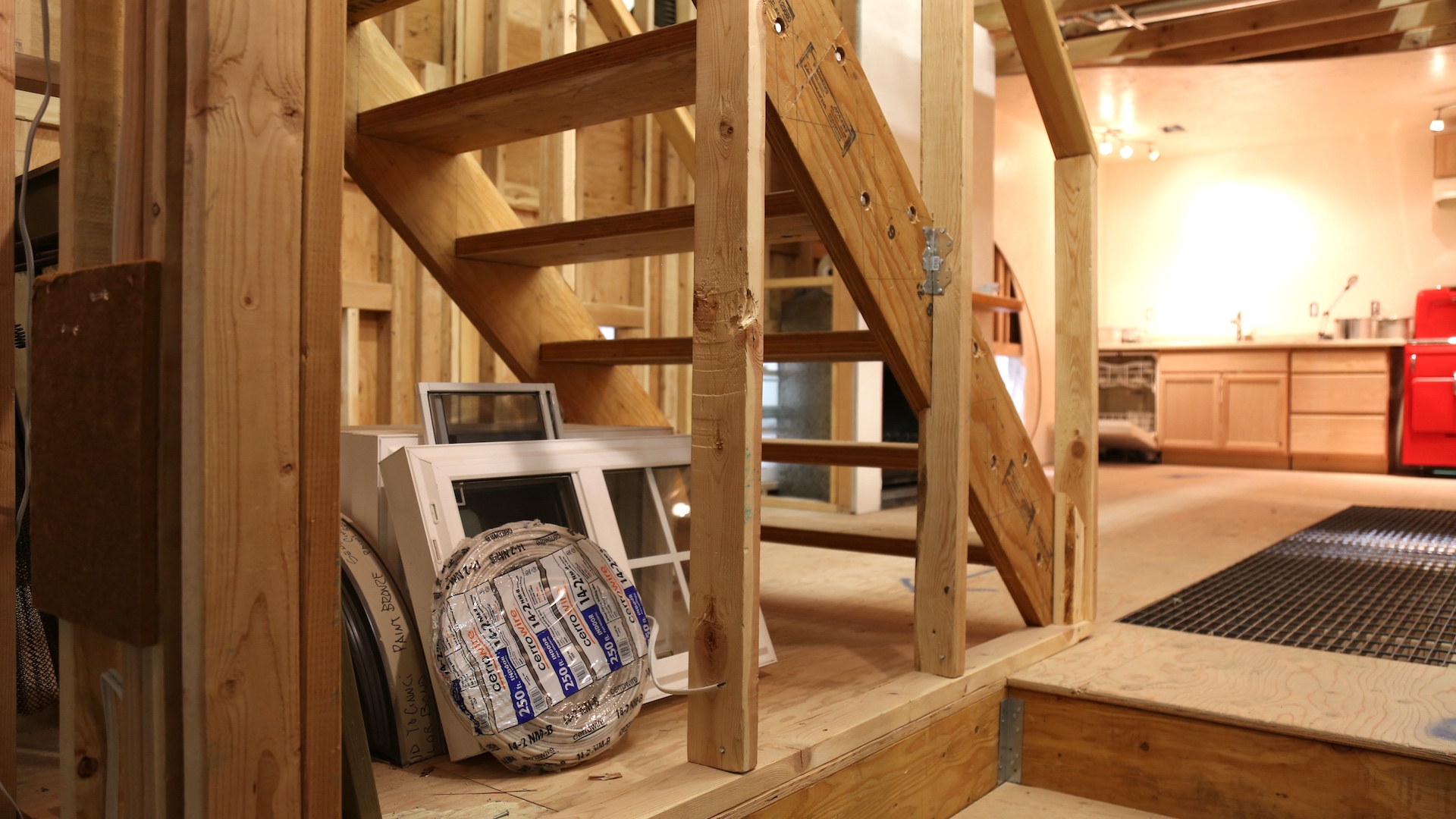
There is missing drywall at the stairs. According to IRC 2015 R302, enclosed accessible space under stairs shall have walls, under-stair surfaces and any soffits protected on the enclosed side with 1/2-inch (12.7 mm) gypsum board.

OBSERVATION #13

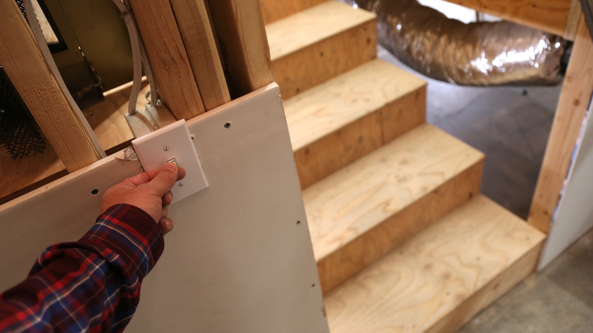
Interior stairways must be provided with an artificial light source to illuminate the landings and treads. There must be a wall switch at each floor level to control the light source where the stairway has six or more risers. The switch for the stairway is located inside the garage. It should be located at the bottom of the stairs without entering the garage.

There is no light fixture for the garage. At least one wall-switch-controlled lighting outlet should be installed in the garage.

OBSERVATION #14

A landing is not required at the top of an interior flight of stairs, including stairs in an enclosed garage, provided that a door does not swing over the stairs.

OBSERVATION #15

There are missing handrails at the stairs from the garage to the house interior. Handrails must be provided on not less than one side of each continuous run of treads or flight with four or more risers.

OBSERVATION #16

Carbon monoxide alarms must be provided in houses where either or both of the following conditions exist:

  • The house contains a fuel-fired appliance.
  • The house has an attached garage with an opening that communicates with the house.

OBSERVATION #17

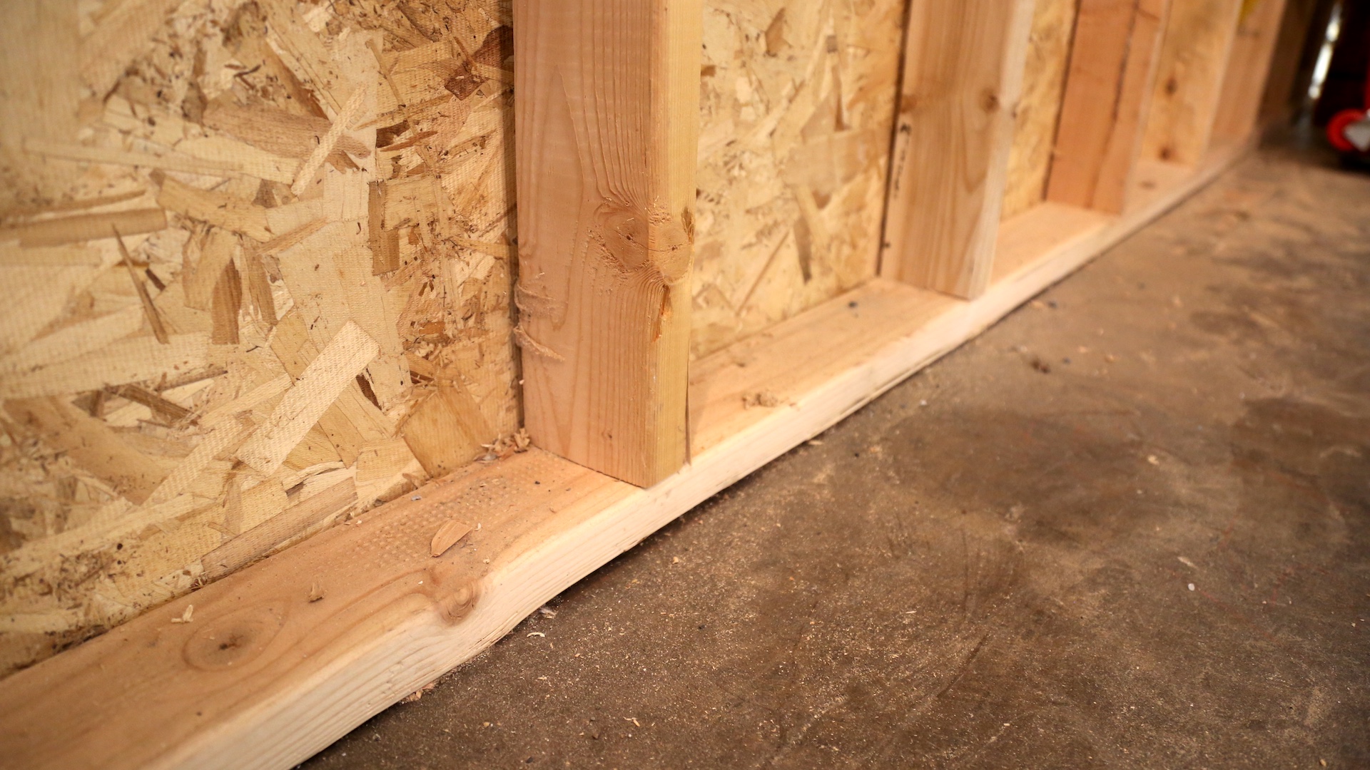
Wood framing members (sole plates) are resting on concrete or masonry slab that is direct contact with the ground. There is no impervious moisture barrier used for separation.

All sill and sole plates must be protected against decay and termites. Protection of wood from decay must be provided by the use of naturally durable wood or wood that is preservative-treated.

All wood in contact with the ground, embedded in concrete in direct contact with the ground, or embedded in concrete exposed to the weather that supports permanent structures intended for human occupancy shall also be of approved preservative-treated wood suitable for ground contact use.

OBSERVATION #18

Wood sill plates should be installed at the garage exterior walls, supported directly on the foundation, and anchored to the foundation. There are no sill plates installed where the wood-framed walls of the garage are supported by the foundation (slab). 

The wood sole plates and wood sill plates at the exterior walls on the monolithic slab must be anchored to the foundation with a minimum 1/2-inch diameter (12.7 mm) anchor bolts. The bolts must be spaced a maximum of 6 feet (1,829 mm) on center. Approved anchors or anchor straps can be installed if they provide equivalent anchorage. The bolts must extend a minimum of 7 inches (178 mm) into concrete or grouted cells of concrete masonry units. The bolt must be located in the middle third of the plate width. A nut and washer might be tightened on each bolt. At least two bolts must be installed on each plate section, with one bolt located no more than 12 inches (305 mm) or less than seven bolt diameters from each end of the plate section. 

The bottom of the stair stringers (at the stairway the lead from the garage to the house interior) that are in direct contact with the concrete slab should be made of naturally durable wood or wood that is preservative-treated. 

OBSERVATION #19

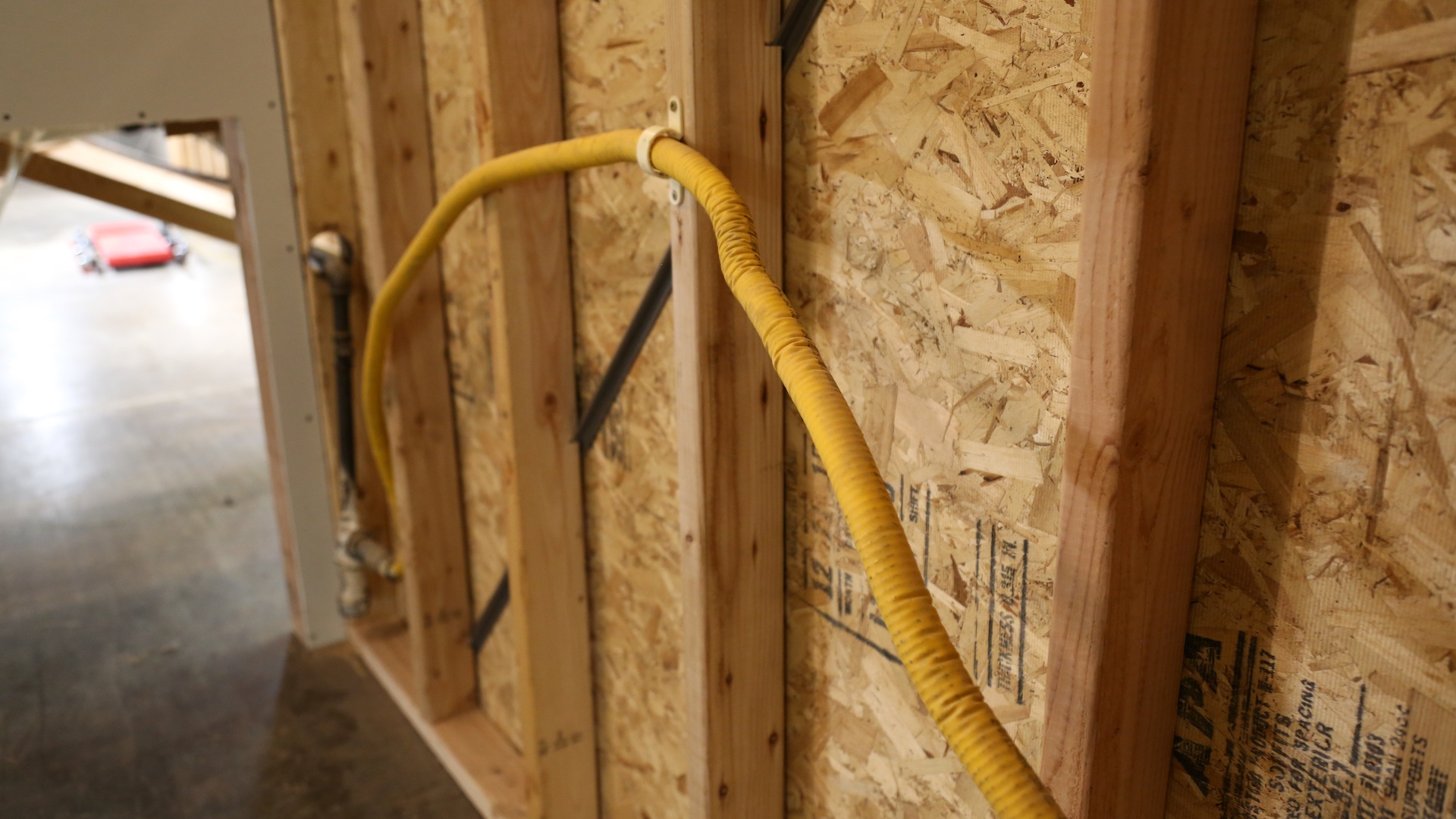
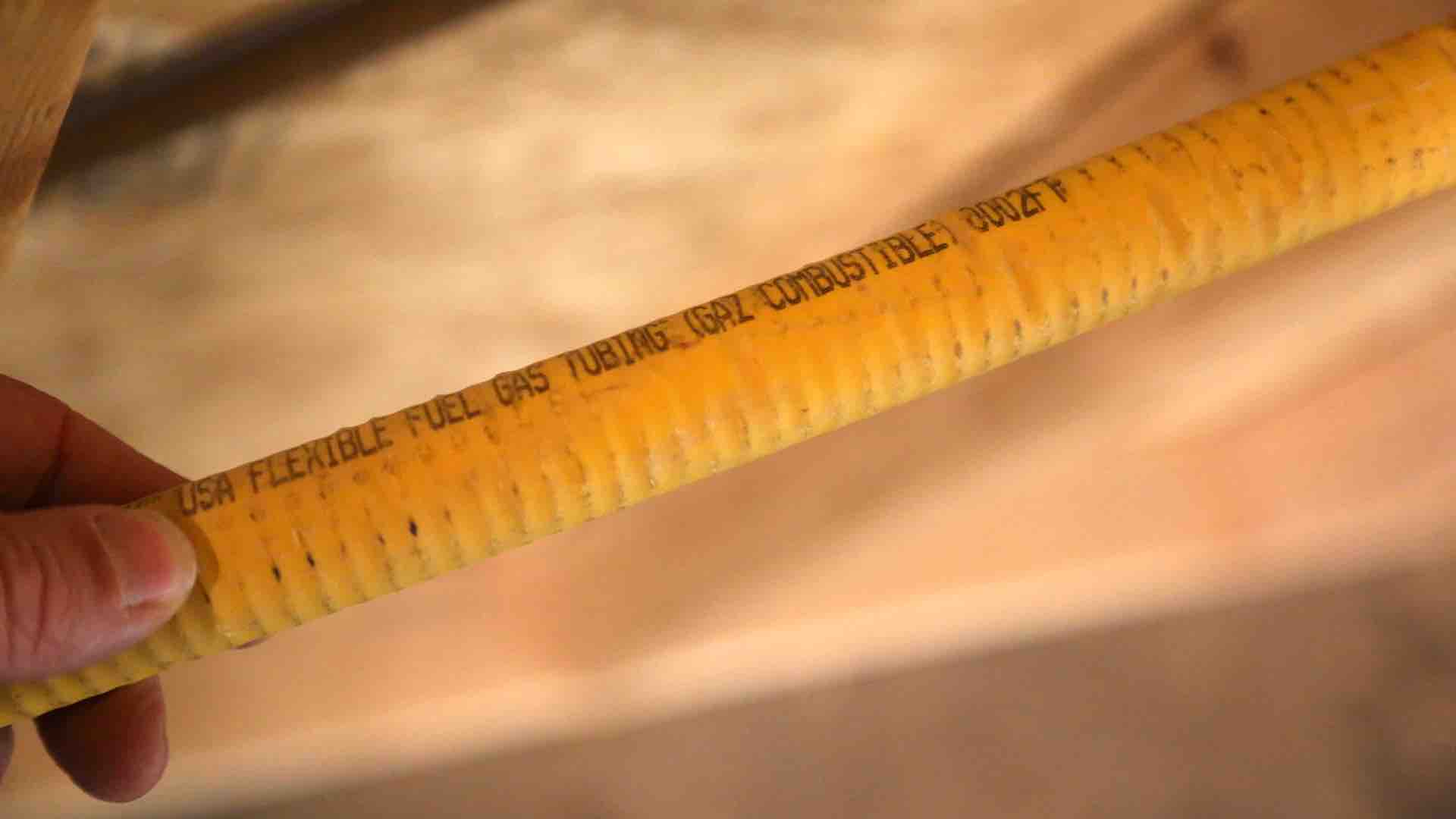
Corrugated Stainless Steel Tubing (CSST) is observed in the garage. CSST piping systems must be installed in accordance with the terms of their approval, the conditions of listing, the manufacturer’s instructions, and the IRC.

CSST is a flexible, stainless steel pipe used to supply natural gas and propane in residential and commercial buildings. It is often coated with a yellow or black plastic coating.  CSST should NOT be confused with flexible gas appliance connectors that join an appliance the gas supply line of a house.

CSST is safe when properly installed.

house-of-horrors-garage-csst-2

The CSST piping is not properly installed for several reasons, including the following:

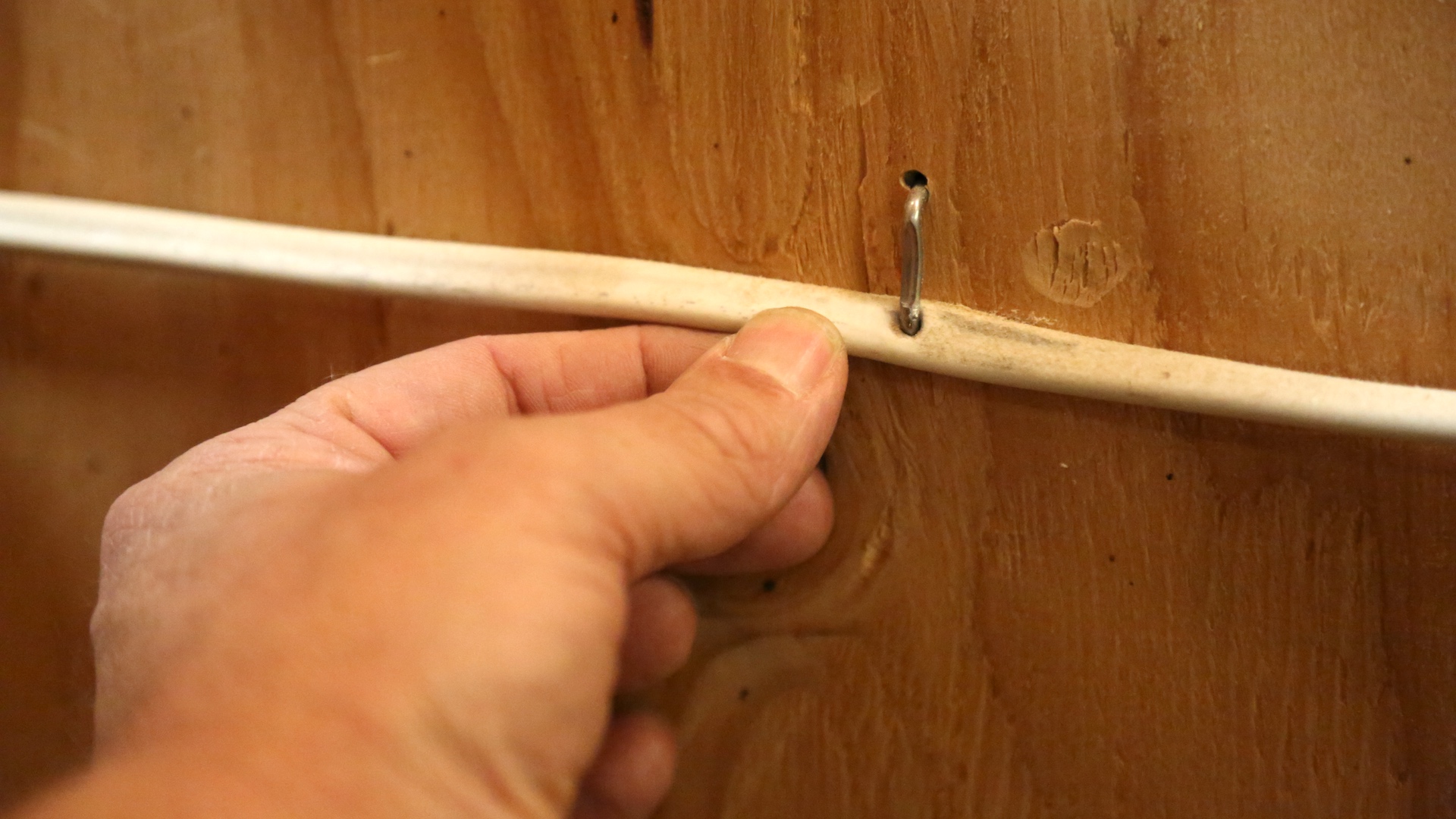
CSST is inadequately supported. CSST is not protected from physical damage. CSST piping installed above ground shall be securely supported and located where it will be protected by physical damage.

Piping shall be supported with hooks, straps, bands, brackets, hangers, or structural components located at intervals so as to prevent or damp out excessive vibration. The piping shall be anchored to prevent undue strains on connected appliances and shall not be supported by other piping. Spacing of supports for CSST should be in accordance with the CSST manufacturer’s instructions, which may be anywhere from 4 to 8 feet intervals.

house-of-horrors-garage-csst-3

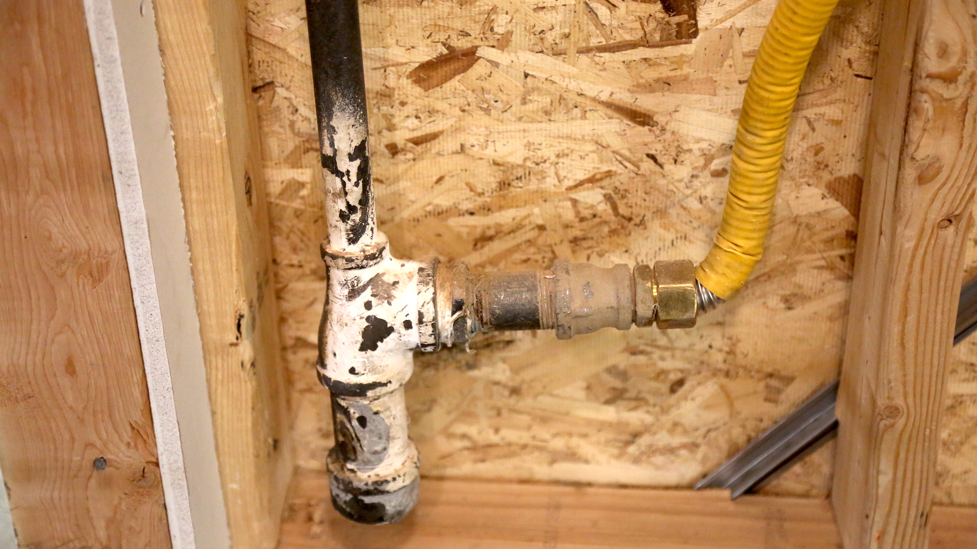
The CSST piping is not properly bonded.

In relation to bonding in the IRC G2411, CSST shall be bonded to the electrical service grounding electrode system or, where provided, the lightening protection electrode system.

  • A bonding jumper shall connect to a metallic pipe, pipe fitting, or CCST fitting.
  • The bonding jumper shall be not smaller than 6 AWG copper wire or equivalent.
  • The length of the bonding jumper between the connection to a has piping system and the connection to a grounding electrode system shall not exceed 75 feet (22,860 mm).
  • NFPA 70 is the standard for bonding connections.

Exposed piping shall be identified by a yellow label marked “Gas” in black letters in intervals of no more than 5 feet (1524 mm).

house-of-horrors-garage-csst-4

The piping should be labeled "Gas".

house-of-horrors-garage-csst-5

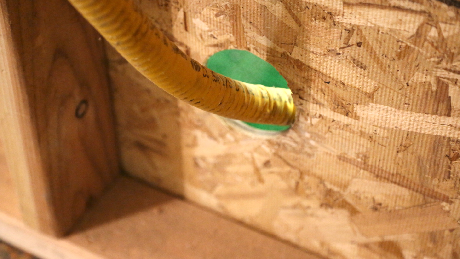
Where passing through an exterior wall, the piping should be protected against corrosion. Where piping is encased in a protective pipe sleeve, the annular space between the piping and the sleeve shall be sealed.

CSST piping must not be installed in or through a duct, clothes chute, chimney or gas vent.

Concealed pipe shall not be located in solid partitions and solid walls, unless installed in a chase or casing. CSST piping must be protected against penetration by fasteners by shield plates where the piping is concealed within the wood-framed wall.

OBSERVATION #20

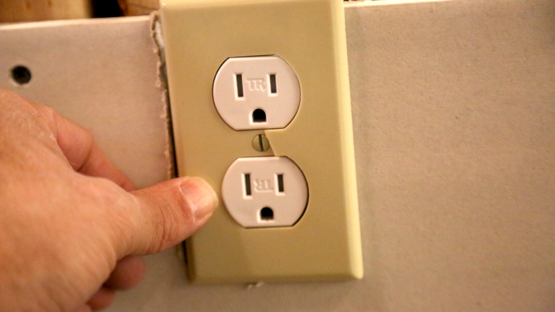
The cover plate at the garage receptacle is cracked.

There is missing GFCI protection at the receptacles in the garage. All 125-volt, single-phase, 15- or 20-ampere receptacles in the garage shall have GFCI ground-fault circuit-interrupter protection for people, according to 2015 IRC E3902 and 2017 NEC 210. It's all receptacles, regardless of it being with reach or readily accessible or not. In the past, it was common to have an appliance supplied by a non-GFCI protected circuit to help prevent nuisance tripping. However, this practice is not longer valid. There's no valid excuse for not having GFCI-protection in any location where the occupants could be at risk of electrical shock.

In a garage, at least one GFCI-protected receptacle outlet should be installed in each vehicle bay and not more than 5.5 feet (1.7 m) above the floor.

2017 NEC 210 also requires that at least one 120-volt, 20-ampere branch circuit be installed to supply receptacle outlets in the garage. Many appliances and tools used in a garage are rated at 12- to 16-amperes or higher and demand at least a 20-ampere rated branch circuit.

OBSERVATION #21

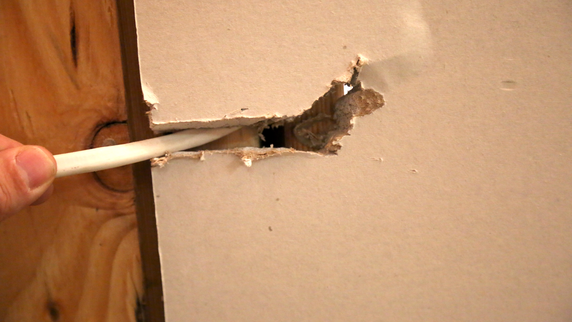
The interior wiring on the back wall of the garage is improperly installed. It is permitted for cables to be exposed, but they must closely follow the surface of the wall. This wiring is loose attached and is not protected from damage. Where subject to physical damage, cables should be protected by rigid metal conduit, EMT electrical metallic tubing, Schedule 80 PVC, or other approved means.

This wiring on the back wall of the garage has created an opening in the drywall through which the wiring passes creating a firewall breach.


OBSERVATION #22

Improper fastening of wiring on garage wall. The staple has also damaged the wiring causing a potential electrical hazardous condition.

OBSERVATION #23

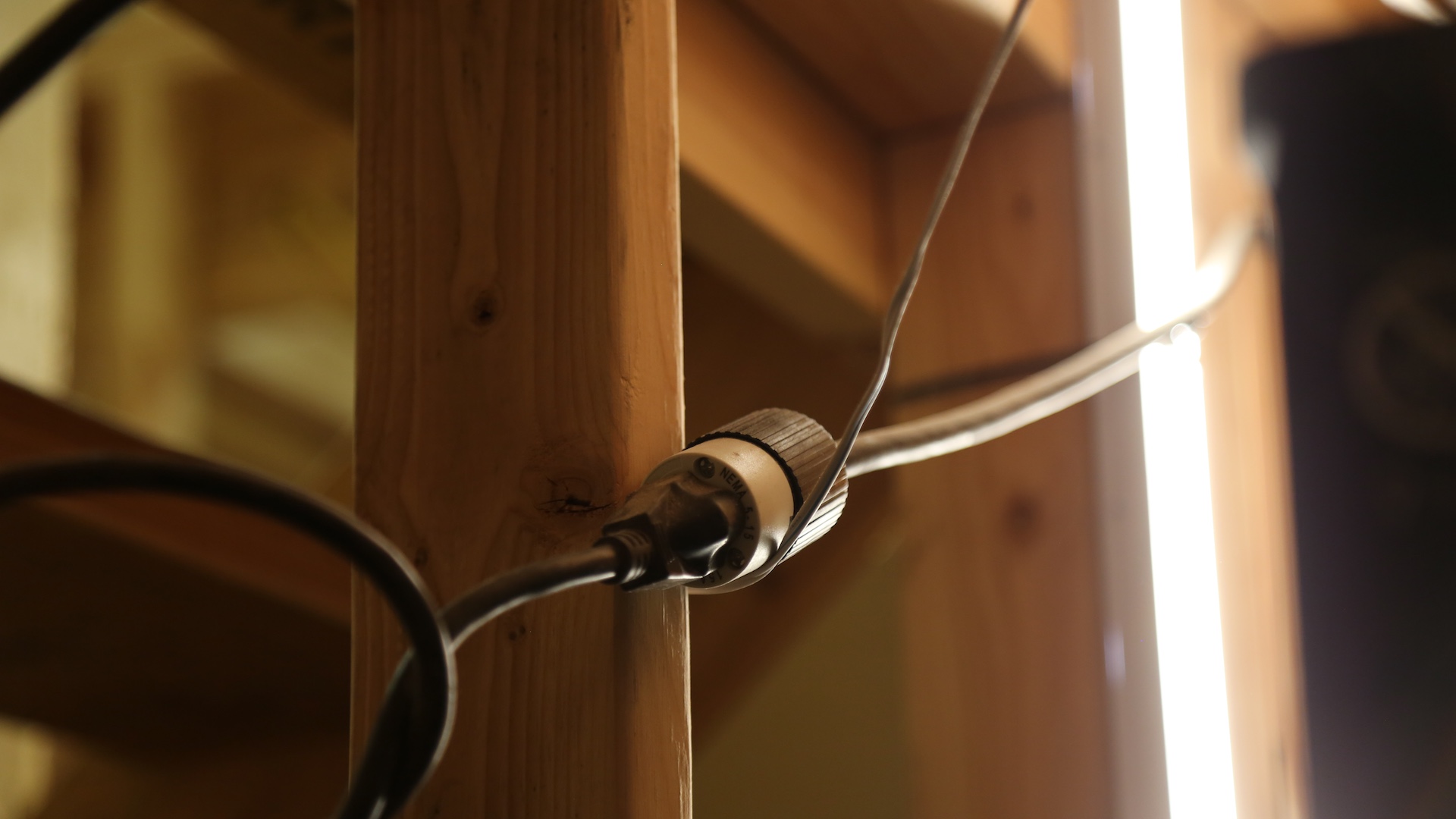
The garage door should not be connected to the electrical supply using an extension cord.


OBSERVATION #24

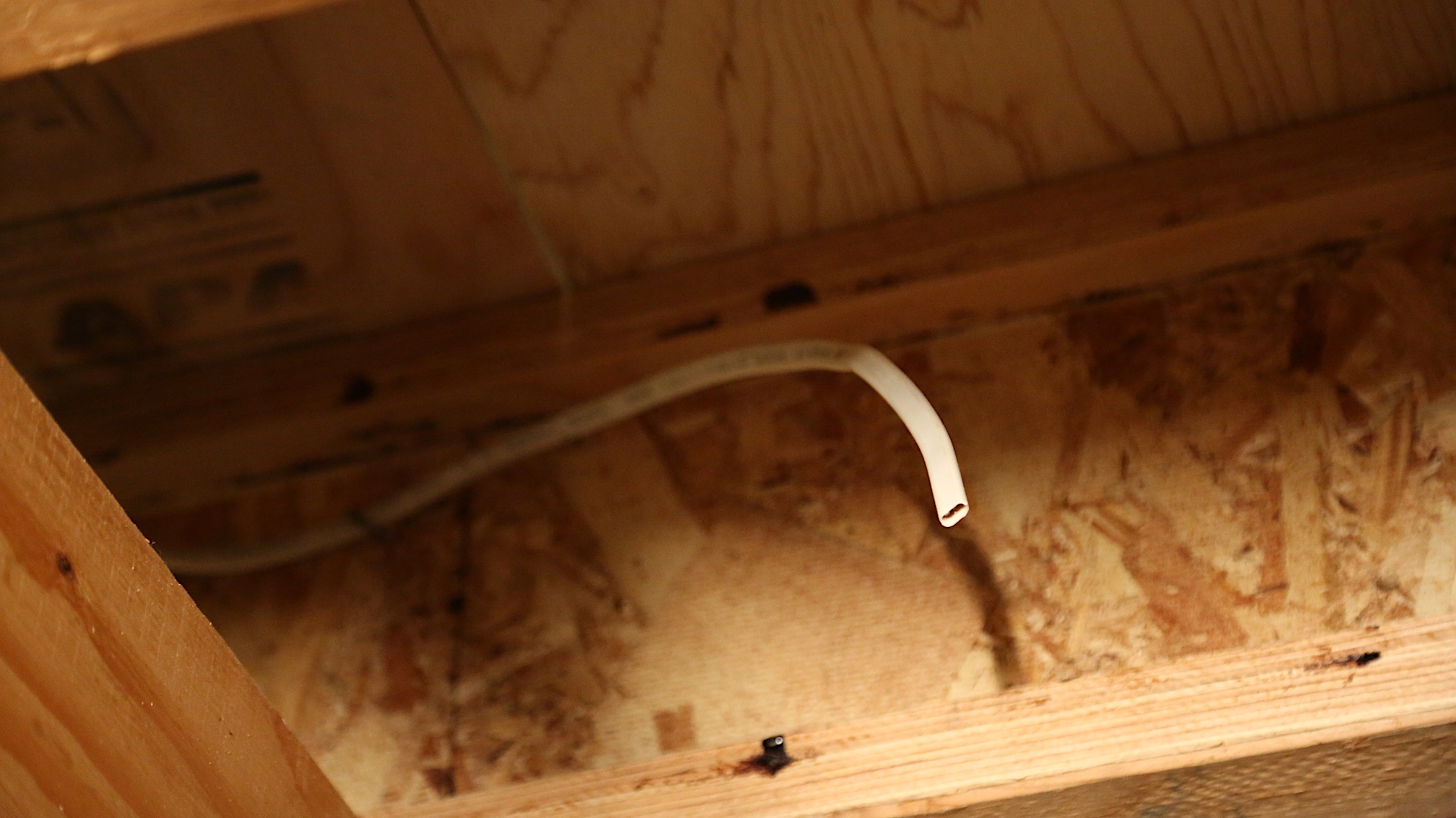
Hazardous condition at the electrical wire hanging from the garage ceiling.

OBSERVATION #25

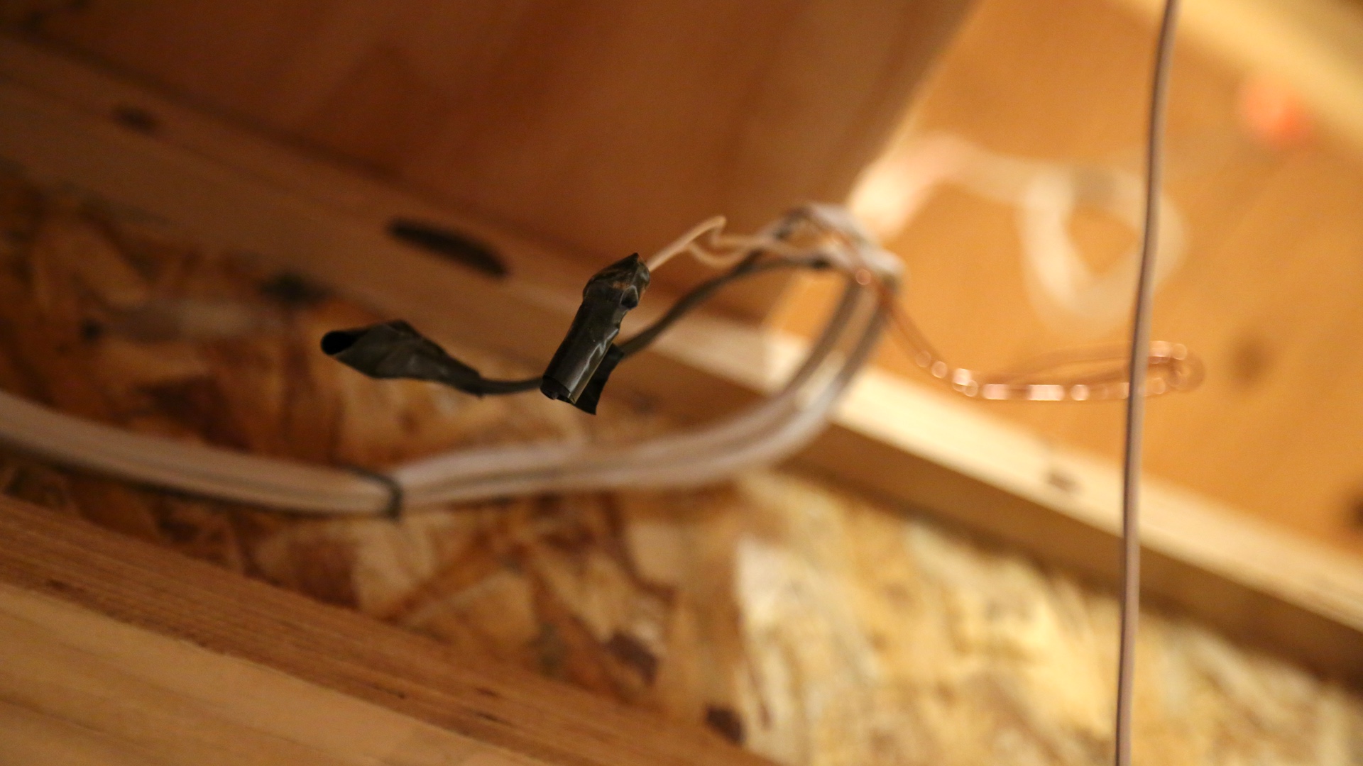
Hazardous condition at the electrical wire hanging from the garage ceiling.

OBSERVATION #26

Missing or damaged light bulbs at the garage door opener machine.

OBSERVATION #27

Garage Door Inspection Procedure

To perform an inspection of the sectional garage doors, you may follow the following inspection procedure.

The garage door is typically the largest moving object in the house, and many of its components are under high tension. Improper installation or maintenance of a garage door can create a hazardous condition that can cause serious injury or even death.

This inspection procedure covers the safest procedures that are supported by DASMA, the Door and Access Systems Manufacturers Association. If you come across a problem with the garage door, recommend that a professional inspect it to make suggestions regarding any necessary corrections.


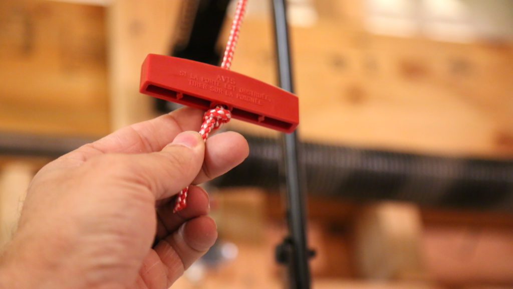
1. Manual Release

house-of-horrors-garage-manual

Begin inside the garage. Have the door closed. Check for a manual release handle, i.e., a means of manually detaching the door from the door opener. The handle should be colored red so that it can be seen easily. The handle should be easily accessible and no more than 6 feet above the garage floor.

2. Door Panels

From inside the garage with the door fully closed, check the condition of the door panels. Check for damage, cracking, denting, bulging and separation of the panels.

3. Warning Labels

The garage doors should have the following warning labels:

  • a spring warning label attached to the spring assembly;
  • a general warning label attached to the back of the door panel;
  • a warning label near the wall control button; and
  • two warning labels attached to the door in the vicinity of the bottom corner brackets. Some newer doors have tamper-resistant bottom corner brackets that do not require these warning labels.

4. Springs and Hardware

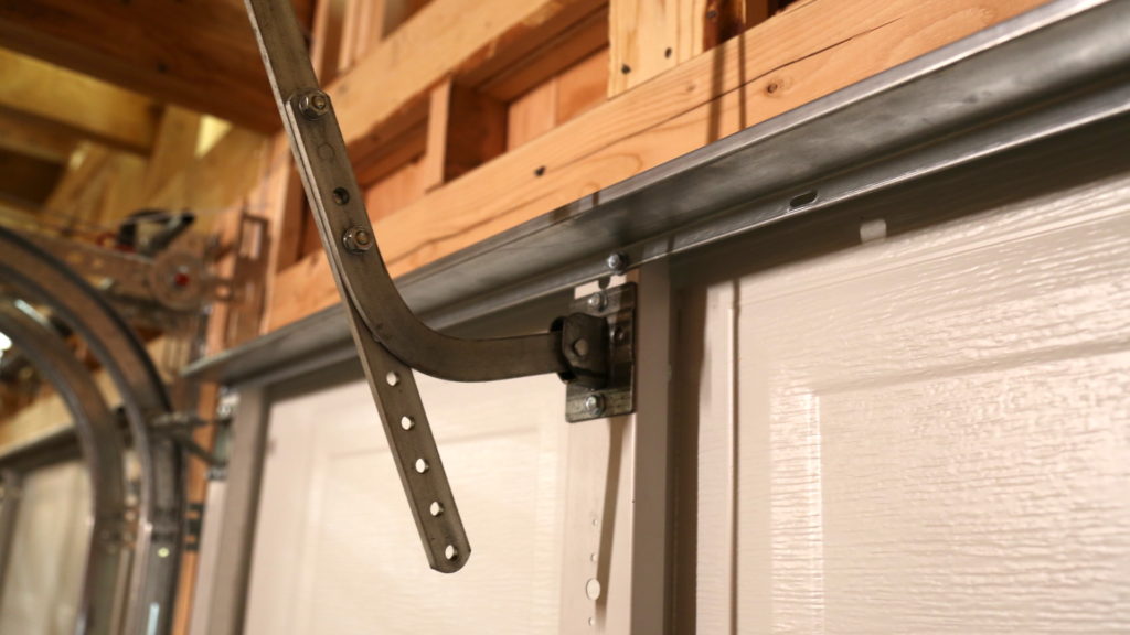
house-of-horrors-garage-bracket

Close the door and check the springs for damage. If a spring is broken, operating the door can cause serious injury or death. Do not operate the door if there is damage. Visually check the door’s hinges, brackets and fasteners. If the door has an opener, the door must have an opener-reinforcement bracket that is securely attached to the door’s top section. The header bracket of the opener rail must be securely attached to the wall or header using lag bolts or concrete anchors.

5. Door Operation

Close the door. If the door has an opener, pull the manual release to disconnect the door from the opener. Lift and operate the door. If the door is hard to lift, then it is clearly out of balance. This is an unsafe condition. Raise the door to the fully-open position, then close the door. The door should move freely, and it should open and close without difficulty. As the door operates, make sure that the rollers stay in the track.

Reconnect the door to the opener, if present. This is generally done by activating the opener until it reconnects itself to the door.

6. Spring Containment

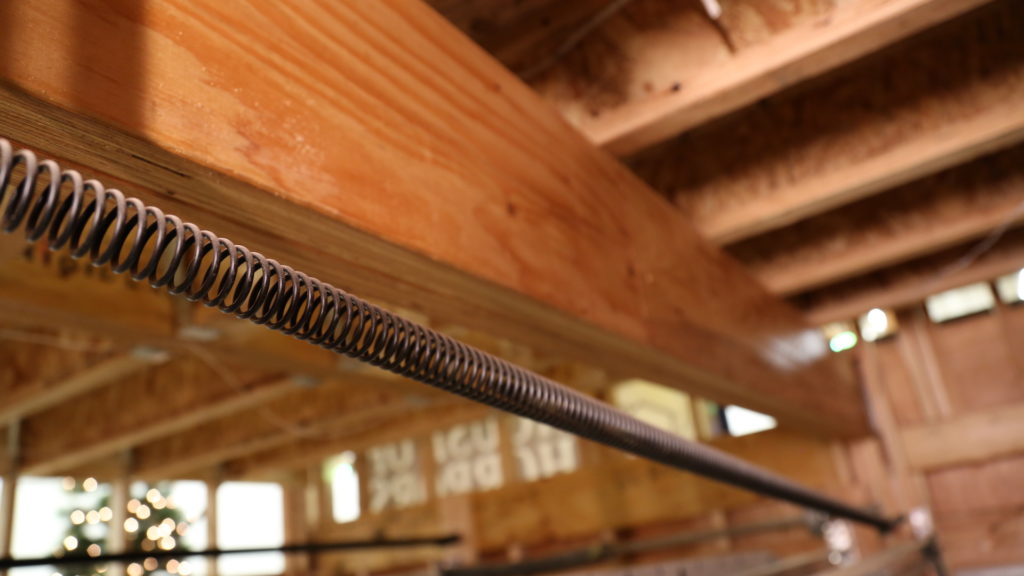
house-of-horrors-garage-containment

The counter-balance system is usually comprised of torsion springs mounted above the door header, or extension springs, which are usually found next to the horizontal track. When springs break, containment helps to prevent broken parts from flying around dangerously in the garage. Torsion springs are already mounted on a shaft, which inherently provides containment.

If the door has extension springs, verify that spring containment is present. Extension springs should be contained by a secure cable that runs through the center of the springs.

7. Wall Push Button

house-of-horrors-garage-button

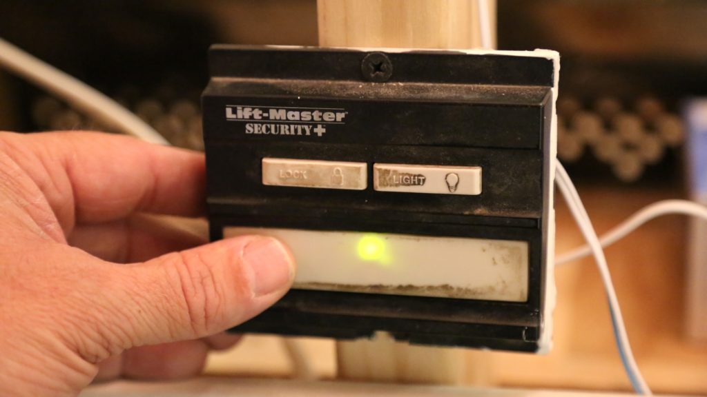
The wall button should be at least 5 feet above the standing surface, and high enough to be out of reach of small children. Press the push button to see if it successfully operates the door.

8. Location of the Photo-Electric Eyes

house-of-horrors-garage-eyes

Federal law states that residential garage door openers manufactured after 1992 must be equipped with photo-electric eyes or some other safety-reverse feature that meets UL 325 standards.

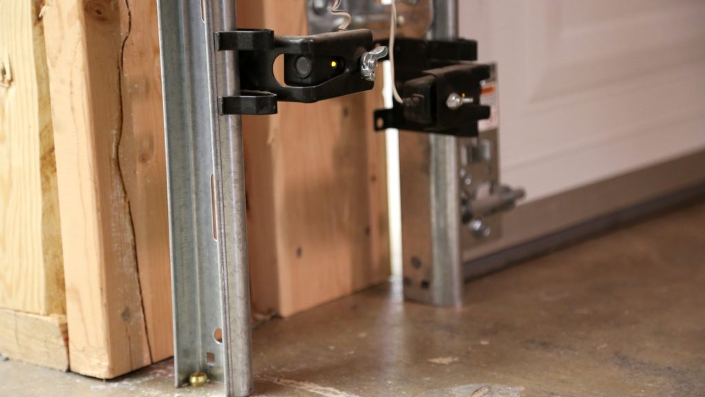
Check to see if photo-electric eyes are installed. The vertical distance between the photo-eye beam and the floor should be no more than 6 inches.

9. Non-Contact Reversal Test

Standing inside the garage but safely away from the path of the door, use the remote control or wall button to close the door. As the door is closing, wave an object in the path of the photoelectric eye beam, such as a 2x4. The door should automatically reverse.


10. Garage Door Labels

Look for labels at the garage door.

The labels provide helpful safety information. Many garage door labels were created using the guidelines of the ANSI-Z535 series of standards regarding the content and format of product safety labels.

The descriptions of the following labels were created by DASMA:

CRGD-100, Garage Door Safety Instructions Safety Label:

This label warns of hazards associated with a garage door. A list of instructions is also given pertaining to safe operation of a garage door. This label should be placed at a readable height on the door.

screen-shot-2016-12-21-at-11-18-53-am

CRGD-101, Garage Door Bottom Bracket Safety Label:

This label warns that a garage door's bottom bracket is under extreme spring tension.  This label should be placed adjacent to a garage door's bottom bracket.

screen-shot-2016-12-21-at-11-19-05-am

CRGD-102, Garage Door Springs Safety Tag:

This two-sided tag warns that garage door springs are under extreme tension. This tag should be affixed directly to a garage door spring assembly such that it does not interfere with spring function.

screen-shot-2016-12-21-at-11-19-23-am


RDD-203, Rolling Door Annual Inspection & Drop Test Record Label:

screen-shot-2016-12-21-at-11-19-36-am